three
6
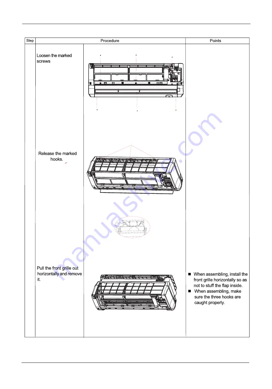
Removal Procedure
4
Domestic Air Conditioner
Remove the casing
1
2
3
All manuals and user guides at all-guides.com
Страница 1: ...o advise non technic al individuals of potentia l dangers in attemptin g to servic e a product Product s powered by electricit y should be service d or repaire d only by experience d professiona l tec...
Страница 2: ...7 3 Specifications 8 4 Sensors list 9 5 Piping diagrams 10 6 Printed circuit board connector wiring diagram 11 7 Functions and control 8 Dimensional drawings 9 Center of gravity 10 Service Diagnosis 1...
Страница 3: ...tic air conditioner 1 Introduction 1 1 Model name explanation G E S N X 2 5 I N Platform of indoor units N N platform 2500W Indoor units Brand Split units 2 G Side closure All manuals and user guides...
Страница 4: ...equipment for a repair Working on the equipment that is connected to a power supply can cause an electrical shook If it is necessary to supply power to the equipment to conduct the repair or inspectin...
Страница 5: ...losed room can cause oxygen deficiency 1 2 2 Cautions Regarding Products after Repair Warning Be sure to use parts listed in the service parts list of the applicable model and appropriate tools to con...
Страница 6: ...t damage or modify the power cable Damaged or modified power cable can cause an electrical shock or fire Placing heavy items on the power cable and heating or pulling the power cable can damage the ca...
Страница 7: ...he room and wet the furniture and floor 1 2 3 Inspection after Repair Warning Check to make sure that the power cable plug is not dirty or loose then insert the plug into a power outlet all the way If...
Страница 8: ...rainage of the indoor unit after the repair Faulty drainage can cause the water to enter the room and wet the furniture and floor 1 2 4 Using Icons Icons are used to attract the attention of the reade...
Страница 9: ...you set the sleep mode during night sleep Super match One outdoor unit can match two or more indoor unit DIY auto mode Adjust the last fixed operation mode automatically Turbo mode Quick cooling or he...
Страница 10: ...P 0 4 2 6 W W P O C S R E E S 147 h W K n o i t p m u s n o c y g r e n e l a u n n A h m l a v o m e R e r u t s i o M TECHNICAL SPECIFICATIONS m m D W H s n o i s n e m i D Packaged Dimensions m m D...
Страница 11: ...ew Proof Temperature control Microcomputer Control M H R Y l e d o m r e l l o r t n o c e t o m e R Note the data are based on the conditions shown in the table below h t g n e l g n i p i P g n i t...
Страница 12: ...Piping diagrams Domestic air conditioner 5 Piping diagrams 10 All manuals and user guides at all guides com...
Страница 13: ...ctor for power L wire 8 CN7 Connector for display board 9 CON1 CON3 Connector for ions generator 10 CN23 Connector for communicate between the indoor board and the outdoor board 11 CN36 Connector for...
Страница 14: ...Printed circuit board connector wiring diagram 12 Domestic air conditioner CN8 CN9 CN6 CN11 CN12 CN31 CN17 CN21 CN18 CN21 CN7 C0N1 CON3 CN23 CN35 CN36 All manuals and user guides at all guides com...
Страница 15: ...15A 250VAC POWER SUPPLY TO OUTDOOR UNIT 1 N C 3 L 2 W B Y G Y G GND CN48 AMBIENT TEMP SENSOR PIPING TEMP SENSOR CN6 CN12 Right stepmotor left stepmotor CN11 R C0N2 BL Fresh air L CN21 N S R W CN18 CN...
Страница 16: ...ll operate at the set speed and the mode signal will be sent to the outdoor system The system will keep the original status if Tr Ts Airflow speed control temperature difference 1 Automatic When Tr Ts...
Страница 17: ...tch Manual When the sensor is off or Tr Ts 3 the manual operation can not be made obligatory automatic operation Airgate location control the location for the airgate can be set according to your need...
Страница 18: ...ue heat sending The indoor fan will send the residue heat at a low speed for 12 seconds If other conditions are satisfied when the compressor stops the indoor system will operate at a light speed The...
Страница 19: ...Timing You can set 24 hours on off timing accordingly After the setting the timing indicator will be lightened Also the light will be turning off after the timing is finished The followings are sever...
Страница 20: ...e urgency key will stop it Under the system off mode the display screen will show automatic running sign Under the system off mode the system will not receive the remote control signal if the press on...
Страница 21: ...e signals for stop According to the signals the malfunction resume presentation finishes The resume restores after the power supply restores 7 1 15 Abnormality confirmation approaches 1 indoor tempera...
Страница 22: ...as the followings Remote control urgency signal operate according to the remote control and the urgent conditions the present status will be stored into the EEPROM of the indoor system Quitting condit...
Страница 23: ...9 19 09 67 4 04 8 130 096 30 18 23 68 3 9 7 122 799 31 17 42 69 3 76 6 115 946 32 16 65 70 3 63 5 109 51 33 15 97 71 3 5 4 103 462 34 15 22 72 3 38 3 97 779 35 14 56 73 3 26 2 92 437 36 13 93 74 3 15...
Страница 24: ...63 1 66 1 54 14 66 3463 61 0123 56 0565 1 64 1 52 13 62 8755 57 9110 53 2905 1 62 1 51 12 59 6076 54 9866 50 6781 1 60 1 49 11 56 5296 52 2278 48 2099 1 58 1 47 10 53 6294 49 6244 45 8771 1 56 1 46 9...
Страница 25: ...76 0 76 27 9 5129 9 2132 8 9148 0 80 0 80 28 9 1454 8 8465 8 5496 0 84 0 83 29 8 7942 8 4964 8 2013 0 87 0 86 30 8 4583 8 1621 7 8691 0 91 0 90 31 8 1371 7 8428 7 5522 0 95 0 93 32 7 8299 7 5377 7 249...
Страница 26: ...1 7908 2 59 2 42 71 2 0337 1 8778 1 7324 2 63 2 46 72 1 9714 1 8186 1 6761 2 68 2 50 73 1 9113 1 7614 1 6219 2 73 2 54 74 1 8533 1 7064 1 5697 2 78 2 58 75 1 7974 1 6533 1 5194 2 83 2 63 76 1 7434 1 6...
Страница 27: ...7641 0 6845 0 6127 4 40 3 97 106 0 7441 0 6661 0 5957 4 46 4 02 107 0 7247 0 6482 0 5792 4 51 4 07 108 0 7059 0 6308 0 5632 4 57 4 12 109 0 6877 0 6140 0 5478 4 63 4 16 110 0 6700 0 5977 0 5328 4 69...
Страница 28: ...Seivice diagnosis Domestic air conditioner 8 Dimensional drawings unit mm 9 Center of gravity unit mm 26 842 211 281 842 281 211 All manuals and user guides at all guides com...
Страница 29: ...tion sometimes stops Check the power supply A power failure of 2 to 10 cycles can stop air conditioner operation Equipment operates but does not cool or does not heat only for heat pump Check for faul...
Страница 30: ...oor EEPROM error Page 30 F1 2 The protection of IPM Page 34 F22 3 Overcurrent protection of AC electricity for the outdoor model Page 35 F3 4 Communication fault between the IPM and outdoor PCB Page 3...
Страница 31: ...or less than 0 08V during compressor Decision operation Conditions z Note The values vary slightly in some models Supposed Faulty connector connection Causes Faulty thermistor Faulty PCB Troubleshoot...
Страница 32: ...M are used to determine MCU Malfunction Detection Malfunction When the data of EEPROM is error or the EEPROM is damaged Decision Conditions Supposed Faulty EEPROM data Causes Faulty EEPROM Faulty PCB...
Страница 33: ...Troubleshooting Caution Be sure to turn off power switch before connect or disconnect connector or else parts damage may be occurred Check whether terminals on indoor pcb is well Electrify the machin...
Страница 34: ...alfunction Detection Malfunction when the data of EEPROM is error or the EEPROM is damaged Decision Conditions Supposed DC fan motor protection dues to the DC fan motor faulty Causes DC fan motor prot...
Страница 35: ...stances between black line 0V and red line 310V between black line 0V and white line 15V of the fan motor NO YES The resistances are greater than 40K NO YES The motor of the outdoor unit is damaged an...
Страница 36: ...to over current Decision The compressor faulty leads to IPM protection Conditions circuit component of IPM is broken and led to IPM protection Supposed IPM protection dues to the compressor faulty Cau...
Страница 37: ...e sure to turn off power switch before connect or disconnect connector or parts damage may be occurred Electrify the machine again and turn it on with the remote controller If malfunctions are reporte...
Страница 38: ...ion Be sure to turn off power switch before connect or disconnect connector or else parts damage may be occurred 1 Check whether Terminal CN23 and CN24 on the outdoor mainboard CN10 and CN11 on IPM mo...
Страница 39: ...ified Causes the IPM module is broken the outdoor PCB is broken Troubleshooting Caution Be sure to turn off power switch before connect or disconnect connector or else parts damage may be occurred Ele...
Страница 40: ...ne again and turn it on with the remote controller then measure the temperature at the exhaust temperature sensor of the compressor on the outdoor unit The temperature exceeds 110 shortly after the ma...
Страница 41: ...ower switch before connect or disconnect connector or else parts damage may be occurred Restart the a c and it becomes normally If starting up normally but malfunction occurs again after a while The o...
Страница 42: ...place it with a new one NO Measure the voltage Between 3 and 4 of IC9 on the Outdoor mainboard with a Multimete The voltage is a constant value of 0V DC to 5V DC The outdoor pcb is damaged replace it...
Страница 43: ...ting Caution Be sure to turn off power switch before connect or disconnect connector or parts damage may be occurred Within 3 minutes after the machine is supplied with power and turned on with the re...
Страница 44: ...ty heat exchange sensor Insufficient gas Troubleshooting Caution Be sure to turn off power switch before connect or disconnect connector or else parts damage may be occurred Electrify the machine agai...
Страница 45: ...10K 1 42 COM1 1 43 DIG1 1 42 COM1 1 43 DIG1 XT1 CSTLS8M00G56 R508 10K R507 10K 1 23 LSTEP_D 1 22 LSTEP_C 1 21 LSTEP_B 1 13 BUZZ 1 15 RSTEP_A 12V 5V J9 J24 E ON OFF J9 J24 ON ON ON EK 387 317 OFF OFF...
Страница 46: ...F C6 0 1uF 0805 C21 0 1uF C31 0 1uF 0805 C34 0 1uF C35 0 001uF E2 100uF 16V 105 E10 100uF 16V 105 C26 0 01uF C41 0 1uF C44 0 001uF C43 0 001uF 2 36 TX 2 35 RX LED1 220V N 5V 5V R4 330 0805 IC2 TLP421...
Страница 47: ...autions to advise non technical individuals of potential dangers in attempting to service a product Products powered by electricity should be serviced or repaired only by experienced professional tech...
Страница 48: ...Removal Procedure 1 Domestic Air Conditioner Removal of front panel front panel Remove the foam cushion 2 Loosen the screw All manuals and user guides at all guides com...
Страница 49: ...Removal Procedure 2 Domestic Air Conditioner Lift up the control box cover 3 Loosen the screw 4 Lift up the control box cover 5 All manuals and user guides at all guides com...
Страница 50: ...n both sides of the unit to remove the front panel Remocal of front panel Removal Procedure 3 Domestic Air Conditioner Pull the wires out of the control box 6 Remove the air filters 1 All manuals and...
Страница 51: ...three 6 Removal Procedure 4 Domestic Air Conditioner Remove the casing 1 2 3 All manuals and user guides at all guides com...
Страница 52: ...horizontal flap flap Removal Procedure 5 Domestic Air Conditioner and the stepper motor Loosen the screws and remove the stepper motor All manuals and user guides at all guides com...
Страница 53: ...2 Every blade go round and round then move it Removal Procedure 6 Domestic Air Conditioner horizontal louver and control box Loosen the screws All manuals and user guides at all guides com...
Страница 54: ...3 7 Domestic Air Conditioner Removal Procedure Loosen the hook and the service Cover Lift up the exchanger and remove it All manuals and user guides at all guides com...
Страница 55: ...Removal Procedure 8 Domestic Air Conditioner motor cover PRWRU FRYHU All manuals and user guides at all guides com...
Страница 56: ...Removal Procedure 9 Domestic Air Conditioner All manuals and user guides at all guides com...