GE
HEALTHCARE
D
IRECTION
2307224-100, R
EVISION
6
D
ISCOVERY
LS S
YSTEM
S
ERVICE
M
ANUAL
Chapter 12 - Troubleshooting
Page 317
12.2.1 Clutch Fails to Engage/Disengage
If the clutch fails to engage or disengage, perform the following checks:
1.) Check whether the E-Stop circuitry was activated. The red lamp on the gantry panel will be
blinking.
a.) E-Stop activation causes clutch to be disengaged. Release the E-Stop button.
b.) If problem persists, proceed to
below.
2.) Perform the following checks:
a.) Disconnect the KBPB Supply Cable, P/N2309061, from the J1 connector.
* Verify that the voltage between the input pins is 120 VAC.
* If 120 VAC is not present, check for proper connection of the other side of the cable
(between Cable P/N 2265683 [Power 120 VAC] and Cable
P/N 2295961 [Table I/F J10 EXT] shown in
b.) Verify proper connections along the complete path of the clutch control signal (Cable P/N
2309062 [KB Box J3 to Gantry], Cable P/N 2309059 [inside the retractor], and Cable P/N
2309066 to ETC Interface).
c.) Verify proper connection of Clutch Power Cable, P/N 2309067, to J4 on the Clutch/Motor.
d.) Check the 200 mA SB fuse on the KB Box chassis.
CAUTION
DISCONNECT J1 POWER BEFORE CHECKING THE FUSE.
3.) If the problem persists, open the KB box cover by unfastening the five screws. Reconnect the
power cable to J1.
CAUTION
DO NOT TOUCH DRIVER BOARD. HIGH VOLTAGE RISK.
4.) Verify that the SSR red LED toggles On and Off when the Cradle Release button is pressed
on the Control panel several times.
a.) If the LED toggles, disconnect the Clutch from the KB Box by disconnecting Cable P/N
2309067 at J4, and measure the voltage between Pins 5 and 6 on the KB Box side.
* This should change from 0 VDC to 130 VDC when the Cradle Release button is
pressed. If the voltage changes, replace the Clutch.
* If the voltage does not change, replace the KB Box.
b.) If the LED does not toggle On and Off when the Cradle Release button is pushed on the
Control panel, check the complete path between J3 on the KB Box and J7 on the ETC
Interface. (This path includes Cables, P/N 2309062, 2309059, and 2309066.)
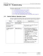
After base axis stops at
limit switch, the workstation
displays the message:
Move table to CT position
.
• Faulty pin locking mechanism.
• Faulty connections of Position
Cable.
• Repair/replace pin locking
mechanism.
• Connect Position cable properly.
(More details in Section
Problem
Likely Cause
Suggested Action/
Replace if Necessary
Содержание Discovery LS
Страница 1: ...GE Healthcare OPERATING DOCUMENTATION 2307224 100 Rev 6 Discovery LS System Service Manual ...
Страница 2: ...GE HEALTHCARE DIRECTION 2307224 100 REVISION 6 DISCOVERY LS SYSTEM SERVICE MANUAL Page 2 ...
Страница 24: ...GE HEALTHCARE DIRECTION 2307224 100 REVISION 6 DISCOVERY LS SYSTEM SERVICE MANUAL Page 24 Table of Contents ...
Страница 32: ...GE HEALTHCARE DIRECTION 2307224 100 REVISION 6 DISCOVERY LS SYSTEM SERVICE MANUAL Page 32 List of Figures ...
Страница 110: ...GE HEALTHCARE DIRECTION 2307224 100 REVISION 6 DISCOVERY LS SYSTEM SERVICE MANUAL Page 110 Chapter 5 Console ...
Страница 222: ...GE HEALTHCARE DIRECTION 2307224 100 REVISION 6 DISCOVERY LS SYSTEM SERVICE MANUAL Page 222 Chapter 6 Table ...
Страница 242: ...GE HEALTHCARE DIRECTION 2307224 100 REVISION 6 DISCOVERY LS SYSTEM SERVICE MANUAL Page 242 Chapter 7 Gantry ...
Страница 357: ......


