GE H
EALTHCARE
D
IRECTION
2307224-100, R
EVISION
6
D
ISCOVERY
LS S
YSTEM
S
ERVICE
M
ANUAL
Page 244
Chapter 8 - System QC, Calibration and Functional Tests
8.1.1.2 Reset the Software Alignment Parameters
The following procedure explains how to reset (set to default values) the software alignment
parameters. The software realignment procedure uses the definition of CT Reconstruction (X, Y,
Pan) and the Z-cradle motion parameters, which it takes from configuration files. (These
parameters should be set to default (resetting any software realignment parameters entered
previously) before starting the mechanical calibration process.)
1.) Set the system into PET mode by clicking the [
PET
] icon on the Image Monitor desktop area.
The Scan Monitor displays the PET main screen.
2.) From the PET main screen, click the [
Full QA
] button.
3.) From the drop-down menu, select
Volumetric QC
. The Volumetric QC panel displays.
4.) From the Volumetric QC panel, click [
Options
], and select
Reset CT Recon Center
from the
drop-down list.
5.) From the Volumetric QC panel, click [
Options
], and select
Reset Plane Offset
from the drop-
down list.
6.) From the Volumetric QC panel, click [
Options
], and select [
Quit Screen
].
7.) Reset the table as follows:
a.) On the Image Monitor, click the [
Service
] button. The
Service Desktop
displays.
b.) From the Service Desktop, click [
System Reset
]. The System Reset screen displays.
c.) Click the [
Scan
] button and then click [
Run
].
8.1.1.3 Positioning the VCQ Phantom
1.) Position the VQC phantom on the cradle on the part marked
VQC Phantom
.
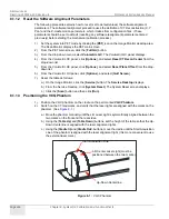
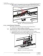
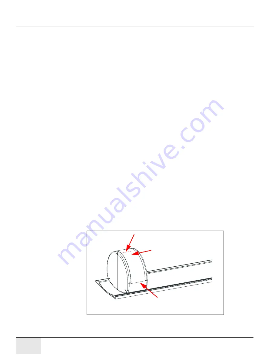
2.) Switch on the CT landmarks, and verify that the laser lights are aligned with the marks on the
phantom. (See
.)
a.) Move the phantom manually until the
L-R Laser Light is symmetrically aligned between the
two marks on the front and the rear sides.
b.) Using the [
Table Up
] and [
Table Down
] buttons, set the height of the table so that the Up-
Down Centerline is aligned with the laser alignment lights.
c.) Using the [
Cradle In
] and [
Cradle Out
> buttons, move the cradle until the Start Acquisition
Line of the phantom is aligned with the laser alignment light. (It is more convenient to use
the external laser mark.)
Figure 8-1:
VQC Phantom
Start Acquisition Line
Up-Down Centerline
L-R Center Laser Light (must be
positioned between the two marks.)
Содержание Discovery LS
Страница 1: ...GE Healthcare OPERATING DOCUMENTATION 2307224 100 Rev 6 Discovery LS System Service Manual ...
Страница 2: ...GE HEALTHCARE DIRECTION 2307224 100 REVISION 6 DISCOVERY LS SYSTEM SERVICE MANUAL Page 2 ...
Страница 24: ...GE HEALTHCARE DIRECTION 2307224 100 REVISION 6 DISCOVERY LS SYSTEM SERVICE MANUAL Page 24 Table of Contents ...
Страница 32: ...GE HEALTHCARE DIRECTION 2307224 100 REVISION 6 DISCOVERY LS SYSTEM SERVICE MANUAL Page 32 List of Figures ...
Страница 110: ...GE HEALTHCARE DIRECTION 2307224 100 REVISION 6 DISCOVERY LS SYSTEM SERVICE MANUAL Page 110 Chapter 5 Console ...
Страница 222: ...GE HEALTHCARE DIRECTION 2307224 100 REVISION 6 DISCOVERY LS SYSTEM SERVICE MANUAL Page 222 Chapter 6 Table ...
Страница 242: ...GE HEALTHCARE DIRECTION 2307224 100 REVISION 6 DISCOVERY LS SYSTEM SERVICE MANUAL Page 242 Chapter 7 Gantry ...
Страница 357: ......


