6 OPTIONS
6.1 OPTIONAL POWER DISTRIBUTION UNIT
A different power distribution unit, equipped with Maintenance Bypass switch, can be installed on the
rear side of the unit.
To replace the Power Distribution Unit (on 5/6 kVA models) or to place the Optional Power Distribution
Unit (on 8/10 kVA models) proceed as follows:
1. Ensure the unit is completely shutdown, with
all breakers opened (see section 4.3.2).
2. Disconnect
internal
batteries (see section
7.4.1 and 7.4.2) and external batteries by
removing cabling from UPS DC connector.
3. On 5/6 kVA models remove all power
connection cables from the Standard PDU
(see section 3.3.9).
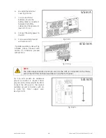
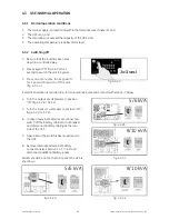
4. On 5/6 kVA models loosen the three mounting
screws (fig. 6.1.a) of the Standard PDU until it
can be removed from the UPS cabinet.
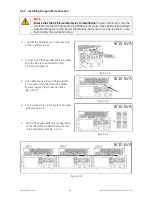
On 8/10 kVA models loosen the four mounting
screws (fig. 6.1.b) of the PDU cover and
remove it.
5. Remove PDU from UPS.
The unit is now ready for new PDU assembly.
fig. 6.1.a
fig. 6.1.b
5/6 kVA
8/10 kVA
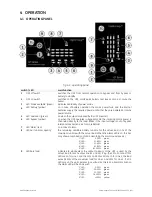
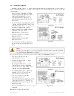
6. On 5/6 kVA models align terminals on the
backside of the PDU with UPS ones and slide
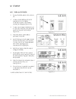
PDU in the UPS (fig. 6.1.c). On 8/10 kVA
connect terminals on the backside of the PDU
with connections in the PDU tray on the
backside of the UPS and slide PDU in to the
UPS (fig. 6.1.d).
7. On 5/6 kVA models fix the PDU to the UPS
with the three mounting screws (fig. 6.1.c). On
8/10 kVA models fix the PDU to the UPS with
the four mounting screws (fig. 6.1.d).
8. Connect Input / Output terminals and follow
standard installation procedure
(see section 3.3.9).
The unit is now ready to be turned on again.
Proceed with section 4.2.1.
fig. 6.1.c
fig. 6.1.d
5/6 kVA
8/10 kVA
modifications reserved
33
User manual GT Series 5/6/8/10 kVA UPS 1.0 (US)

