290
D90
PLUS
LINE DISTANCE PROTECTION SYSTEM – INSTRUCTION MANUAL
CONTROL ELEMENTS
CHAPTER 7: PROTECTION
The following settings are available for the direct under-reaching transfer trip (DUTT)
scheme.
Function
Range: Enabled, Disabled
Default: Disabled
This setting enables and disables the direct under-reaching transfer trip (DUTT) scheme.
Seal-In Delay
Range: 0.000 to 65.535 seconds in steps of 0.001
Default: 0.000 seconds
The DUTT OP FlexLogic™ operand is produced according to the scheme logic. A seal-in
time delay is applied to this operand for coping with noisy communication channels
such as a power line carrier. This setting specifies a minimum guaranteed duration for
the
DUTT OP
pulse. As this operand activates the trip table of the DUTT scheme, the trip
operands (
DUTT TRIP A
,
DUTT TRIP B
,
DUTT TRIP C
, and
DUTT TRIP 3P
) are sealed-in for the
same period of time.
Communication Bits
Range: 1, 2, 4
Default: 2
This setting specifies the number of bits available on the communications channel. With
only one bit available, the scheme sends the direct under-reaching transfer trip
command on bit 1 (the
DUTT TX1
operand) and responds to the direct trip command
received on bit 1 (the
RX1
setting). The scheme uses only local fault type identification
provided by the phase selector to assert the trip operands (
DUTT TRIP A
,
DUTT TRIP B
,
DUTT
TRIP C
, and
DUTT TRIP 3P
).
RX1, RX2, RX3, RX4
Range: any FlexLogic™ operand
Default: OFF
These settings allow the user to select the FlexLogic™ operands that represent the
receive signals for the scheme. Typically input contacts interfacing with a signaling
system are used.
The DUTT scheme requires a secure and dependable signaling system. For this reason, a
series-parallel combination of receive signal contacts is often used. This is accomplished
by using a multi-bit communications system to transmit redundant copies of the
transmit signal (often via different paths) and building appropriate security logic (such as
series (AND gate) or two-out-of-three voting logic) with FlexLogic™. The
RX1
to
RX4
settings should be associated with the final (secure) transmit signals.
These settings are used in the following manner.
–
Single bit applications: only
RX1
is used.
–
Two-bit applications:
RX1
and
RX2
must be used.
–
Four-bit applications:
RX1
through
RX4
must be used.
In multi-terminal applications, the receive signals from two or more remote terminals
should be connected through OR gates in protection FlexLogic™ and the resulting
signals configured as the RX1 through
RX4
settings.
Events
Range: Enabled, Disabled
Default: Enabled
This setting enables and disables the logging of direct under-reaching transfer trip
(DUTT) scheme events in the sequence of events recorder.
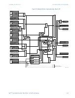
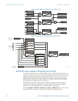
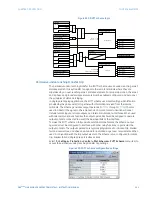
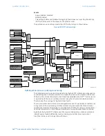
The direct under-reaching transfer trip (DUTT) scheme logic is shown below.
Содержание D90 Plus
Страница 10: ...x D90PLUS LINE DISTANCE PROTECTION SYSTEM INSTRUCTION MANUAL TABLE OF CONTENTS ...
Страница 438: ...428 D90PLUS LINE DISTANCE PROTECTION SYSTEM INSTRUCTION MANUAL PROTECTION FLEXANALOG PARAMETERS CHAPTER 7 PROTECTION ...
Страница 502: ...492 D90PLUS LINE DISTANCE PROTECTION SYSTEM INSTRUCTION MANUAL AUTOMATION FLEXANALOG PARAMETERS CHAPTER 8 AUTOMATION ...
Страница 626: ...616 D90PLUS LINE DISTANCE PROTECTION SYSTEM INSTRUCTION MANUAL ENERVISTA SECURITY MANAGEMENT SYSTEM CHAPTER 13 SECURITY ...
Страница 678: ...668 D90PLUS LINE DISTANCE PROTECTION SYSTEM INSTRUCTION MANUAL SINGLE POLE TRIPPING CHAPTER 15 THEORY OF OPERATION ...
Страница 684: ...674 D90PLUS LINE DISTANCE PROTECTION SYSTEM INSTRUCTION MANUAL DISPOSAL CHAPTER 16 MAINTENANCE ...
Страница 686: ...676 D90PLUS LINE DISTANCE PROTECTION SYSTEM INSTRUCTION MANUAL REVISION HISTORY CHAPTER 17 APPENDIX ...

