background image

User’s Manual

78

Manageable 8/9-Port Switch

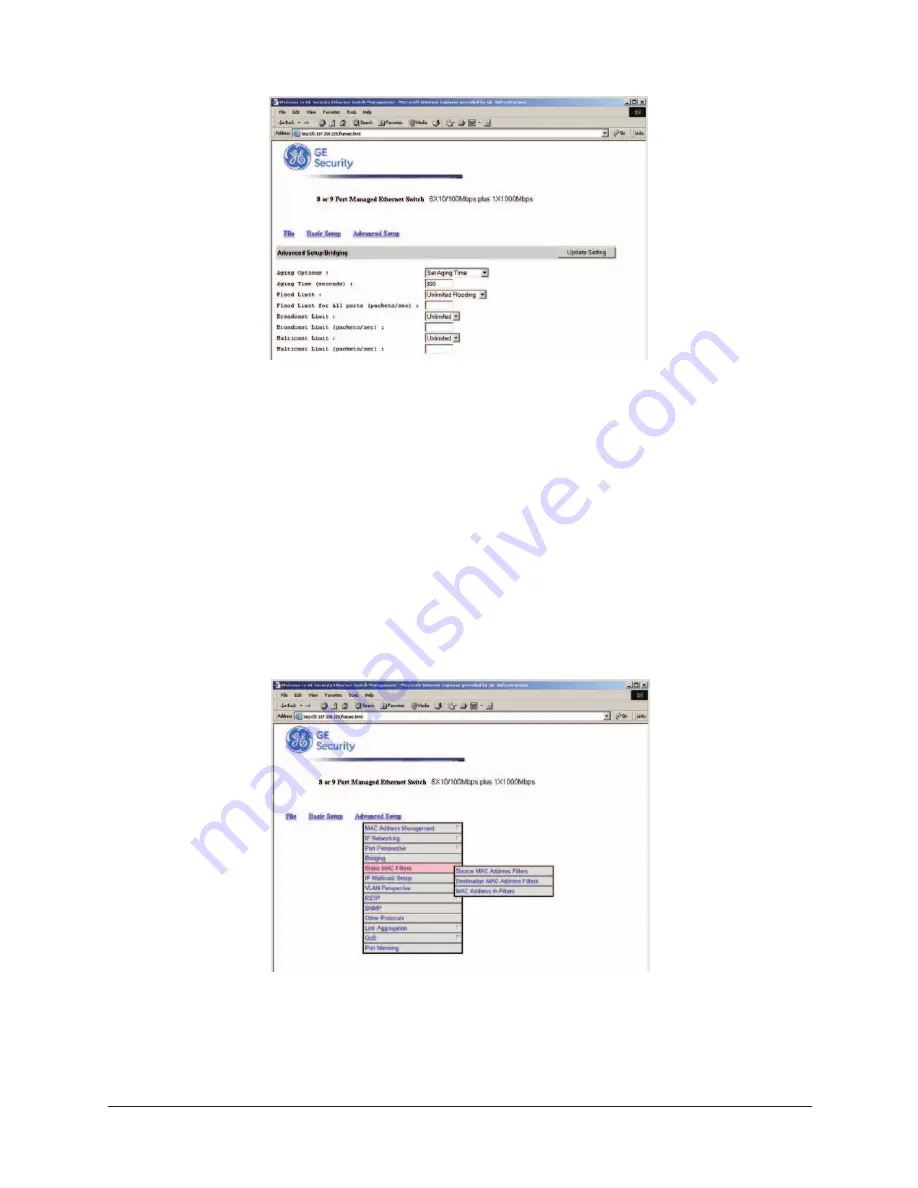
Step 2: Aging Options  

Click the drop-down list for

Disabled 

(No Aging) o

r Set Aging Time.

Step 3: Aging Time  

Click the text box and type a decimal number as bridge aging period in seconds. 

Step 4: Flood Limit  

Click the drop-down list for

No Flooding, Controlled Flooding, Unlimited Flooding.

Step 5: Flood Limit for All Ports  

Click the text box and type a decimal number as flood limit in packets per second.

Static MAC Filter

To access the static MAC filter parameters, click the

Advanced Setup 

button, and point to

Static

MAC Filter 

in the selection menu.

Step 1: Source MAC Address Filter  

Click 

Source MAC Address Filters.

Step 2: 

Click 

Add MAC Addr

button to add a source MAC address for static filtering. 

Содержание D-GES7600 Series

Страница 1: ...D GES7600 Series Installation Operation Instructions managed ethernet switches GE Security ...

Страница 2: ... switching technology with SNMP RMON web based management functions The D GES7600 series brings a simple answer to today s complicated networking environments To get the most out of this manual you should have an understanding of Ethernet networking concepts In this manual you will find Features on the Switch Illustrative LED functions Installation Instructions Management Configuration SNMP Specif...

Страница 3: ... Enhanced Security 9 VLAN Membership 9 VLAN Configuration 10 Intra VLAN Communication 10 Inter VLAN Communication 10 GVRP 10 IGMP Snooping and IP Multicast Filtering 10 Switch Management 11 INSTALLATION 12 Selecting A Site For The Switch 12 Methods for Mounting the D GES7600 12 15 Connecting To Power 16 Power On Self Test POST 16 Connecting To Your Network 17 Cable Type Length 17 SWITCH MANAGEMENT...

Страница 4: ...ment Activities 33 62 Sending and Receiving Files 63 64 Logout 65 Save Settings 65 Restore Default Settings 65 Reboot 65 WEB BASED BROWSER MANAGEMENT 66 Logging On To The Switch 66 Understanding The Browser Interface 67 Performing File Activities 68 To Perform File Activities 68 Performing Basic Setup Activities 69 To Perform Basic Setup Activities 69 73 Performing Advanced Setup Activities 74 To ...

Страница 5: ... SC connectors up to 15 km for 100FX 10km for 1000FX Auto negotiation for speed and duplicity on all TX ports Store and Forward mechanism Back pressure and IEEE 802 3x compliant flow control Supports 4K MAC addresses Redundant power supply connections Optional TX or FX 1000Mbps aggregation port Optional contact closure for fiber loss alarm Manageable 8 9 Port Switch PRODUCT OVERVIEW 100FX Optical ...

Страница 6: ...roring Port mirroring provided through dedicated port Port 1 Internet Working Protocols Bridging 802 1D Spanning Tree 802 1P Q GARP GVRP IP Multicast IP Multicast Packet Filtering Network Management Methods Console port access via RS 232 cable Telnet remote access SNMP Agent MIB 2 RFC1213 Bridge MIB RFC1493 RMON MIB RFC1757 statistics history alarm events VLAN MIB 802 1Q RFC2674 Private MIB Web br...

Страница 7: ...connected to power 2 Optical Status LED s FX The ACT LED s come on when data is present LED will flash at the rate data is transferred The LNK LED s will be on for 100FX speed transmission 3 10 100 1000TX Port Status LED s The LED s are located at each port displaying status Please refer to the Table for more details LED State Indication GREEN YELLOW Steady A valid network connection established F...

Страница 8: ... 1000TX and or 100 1000FX combinations ports CONNECTIVITY RJ 45 connectors SC connector on fiber ports MODE SELECTION 10BaseT full duplex mode 10BaseT half duplex mode 100BaseTX full duplex mode 100BaseTX half duplex mode 100BaseFX full duplex mode 100BaseFX half duplex mode 1000BaseTX full duplex mode 1000BaseTX half duplex mode 1000BaseFX full duplex mode 1000BaseFX half duplex mode Auto sensing...

Страница 9: ...E I Half duplex mode uses back pressure flow control to prevent the receiving buffer from being overrun by data from a source node II Full duplex mode uses 802 3x flow control standard to prevent fast data traffic from overrunning slow data traffic III Auto sensing mode is in use after auto negotiating with the other end of the link UNICAST SWITCHING VLAN CLASSIFICATION When the switch receives a ...

Страница 10: ... ID in the SDB and modifies its management database MDB accordingly FILTERING After learning the address the switch checks Whether the source port or destination port is in the forwarding state Whether the source MAC address or destination MAC address is to be filtered Whether the source port ID is the same as destination port ID If any of these conditions are met the switch drops the receiving Ot...

Страница 11: ...destination MAC address is to be filtered If any of these conditions are met the switch drops the receiving Otherwise it continues with the forwarding process described below FORWARDING The D GES7600 floods the received multicast frame to all ports that are in the forwarding state within the VLAN excluding the source port At the same time the switch ascertains the individual ports VLAN tagging unt...

Страница 12: ...imited by the hardware constraints that physically connect traditional LAN segments to a network they can define a network into various logical configurations For example VLANs can define a network by function In this setting a system integrator might create one VLAN for multimedia users and another for email users VLANs can also define a network by location or type of service For example a locati...

Страница 13: ...vice in another VLAN the traffic must go through a router VLAN MEMBERSHIP VLAN implementation allows Up to 64 VLANs in one switch VLANs across multiple switches by using explicit or implicit tagging and the GARP GVRP protocol defined in IEEE802 1p and 802 1Q An end station s network interface card belongs to multiple VLANs A switch port to be associated with multiple VLANs DEFINITIONS OF VLAN MEMB...

Страница 14: ...nctions section INTER VLAN COMMUNICATION The switch supports Inter VLAN communication using CPU based routing software GVRP GARP VLAN Registration Protocol IGMP SNOOPING AND IP MULTICAST FILTERING In addition to network management tools that allow network administrators to statically add and delete VLAN member ports the routing switch supports GARP VLAN Registration Protocol GVRP GVRP supports dyn...

Страница 15: ...uters instead of flooding to all ports in the subnet VLAN Routing switches with IP multicast filtering switching capability not only run passively monitor IGMP Query and Report messages DVMRP Probe messages PIM and MOSPF Hello messages they also actively send IGMP Query messages to learn locations of multicast routers and member hosts in multicast groups within each VLAN Note however IGMP neither ...

Страница 16: ...s than 95 percent non condensing Surrounding electrical devices should not exceed the electromagnetic field RFC standards for EIC 801 3 Level 2 3V M field strength Make sure that the switch receives adequate ventilation Avoid blocking the ventilation holes on all sides of the switch Methods for Mounting the D GES7600 Several mounting configurations are available for the variety of applications for...

Страница 17: ...elow DIN Rail Side Mounting DS Option The bracket provided will require the removal and re installation of one cover screw the other screws are provided with the bracket as shown below Bracket DB Option Cover Screws Note Bracket is mounted on the Power Supply Side Right Side of the switch Bracket DS Option D GES7600 Unit 10 100 Port Side Cover Screw Provided Mounting Screws ...

Страница 18: ...ingle Unit RS Option The brackets provided have screws included for proper mounting as shown below Note All screws must be fastened and secured to insure adequate stability and strength Mounting Screws 4 Locations Provided Brackets RS Option Top View Front View ...

Страница 19: ...er s Manual 15 Rack Mounting Dual Units RD Option The brackets and braces provided have screws included for proper mounting as shown below Brackets 2 Provided Mounting Screws Brace Locations Front View Brace 2 Provided Bottom View ...

Страница 20: ...y must be equal to or less than the potential of the primary supply To Primary Wall Supply To Secondary Supply Secondary B Power Connector Primary A Power Connector D7600 MM E CC Shown Power On Self Test POST The switch performs its Power On Self Test POST when the power is applied to the switch During the POST the switch CPU will Perform a series of diagnostic procedures to make sure the basic sy...

Страница 21: ...00 Mbps MMF 50 or 62 5µm 25dB Return Loss Minimum 100BaseFX 100BaseFX HP 100BaseFX HP1 SC 37 km 54 km 97 km 100 200 Mbps SMF 9 or 10µm 25dB Return Loss Minimum 1000BaseFX SC 28 km 500 1000 Mbps SMF 9 or 10µm 25dB Return Loss Minimum 10BaseTX 1000BaseTX RJ 45 100 m 100 200 Mbps 2 Pair UTP STP Cat 5 5E 6 Cabling Step 1 First ensure the power of the switch and end devices are turned off NOTE Always e...

Страница 22: ...o contains information about port connection options This section covers the following topics Management Access Overview Key Concepts Key Guidelines for Implementation Administration Console Telnet Access Web Management Access SNMP Access Standards Protocols and Related Reading MANAGEMENT ACCESS OVERVIEW The EtherNav D GES7600 switch gives you the flexibility to access and manage the switch using ...

Страница 23: ...n Most visually appealing Disadvantages Security can be compromised hackers need only know the IP address and subnet mask May encounter lag times on poor connections Telnet Interface The connection is the same as Web Based Browser Interface but with Console Port Hyper Terminal type user interface External SNMP Based Network Management Application Advantages Communicates with functions at the MIB l...

Страница 24: ... using the management method configure the terminal emulation program to use the following parameters you can change these settings after login Default Parameters 115 200bps 8 Data Bits No Parity 1 Stop Bit Flow Control None This management method is often preferred because you can remain connected and monitor the system during systems reboots Also certain error messages are sent to the Console po...

Страница 25: ...ter or Netscape Navigator 4 03 or later Netscape Navigator If you use Netscape Navigator 4 03 or 4 04 install the Netscape JDK 1 1 Patch Download the patch from http help netscape com filelib html smartupdate If you encounter problems accessing Help files when you use Netscape clear the browser memory cache and disk cache and restart the browser Internet Explorer If you use Internet Explorer insta...

Страница 26: ... TCP IP you must have at least one IP address configured on the switch before you can establish access to it with a virtual terminal protocol Note Terminal emulation is different from a virtual terminal protocol in that you must connect a terminal directly to the console port Simple Network Management Protocol SNMP SNMP is the standard management protocol for multi vendor IP networks SNMP supports...

Страница 27: ...The Switch At the screen prompt Switch Console Login Password Login Name Enter the console interface factory default console name admin Password Enter the factory default password ethernav press Enter directly Or enter a user defined password if you followed the instructions later and changed the factory default password Factory Default Password ethernav press Enter directly NOTE Only one console ...

Страница 28: ...ming advanced management activities Logout Highlight this option and press enter to log out Save Settings Highlight this option and press enter to save the current settings and remain in the configuration program Restore Default Settings Highlight this option and press enter to restore the factory default settings Reboot Highlight this option and press enter to reboot ...

Страница 29: ...anageable 8 9 Port Switch Press this key To Up Arrow or K Move the highlight one line up in a menu box Down Arrow or J Move the highlight one line down in a menu box Tab Move the highlight between screens Enter Select the highlighted option Esc Move to a previous menu PERFORMING BASIC MANAGEMENT ACTIVITIES Navigating Through the Console Interface The console interface consists of a series of menu ...

Страница 30: ... option and press enter Or press esc to EXIT NOTE The changes will be effective after you press the esc but will not be saved until you select the Save Setting function GENERAL MANAGEMENT CONFIGURATIONS Step 1 Highlight General from Basic Management screen and press enter ...

Страница 31: ...u want to change it Step 6 Statistics Collection Move to highlight Statistics Collection and press enter If you want to change it Disabled or Enabled Step 7 Reboot on Error Move to highlight Reboot On Error and press enter If you want to change it Disabled or Enabled Step 8 Remote Telnet Login Move to highlight Remote Telnet Login and press enter if you want to change it Disabled or Enabled Step 9...

Страница 32: ...Basic Management screen and press enter Step 2 Speed Flow Control Speed Flow Control is highlighted Press enter if you want to set speed or flow control on port Step 3 Highlight All Ports and press enter to configure at one time Or move to highlight each port and press enter to configure individually ...

Страница 33: ... setting from Speed Options and press enter Note In the Speed Options HD denotes half duplex and FD denotes full duplex Step 6 Press esc to previous screen Highlight Flow Control and press enter Step 7 Flow Control For Flow Control move to highlight a desired setting from Flow Cntl Options and press enter User s Manual 29 Manageable 8 9 Port Switch ...

Страница 34: ...ansmission To allow transmission on the port move to highlight Up from the options in Step 10 Step 12 Physical Port Address Press esc to a previous screen as shown in Step 1 Step 13 Move to highlight Physical Address to view physical port address Step 14 Return to Basic Management Press esc to return to Basic Management screen when completed Step 10 For Admin Control move to highlight Up or Down f...

Страница 35: ...s enter if you want to change the current console baud rate Step 3 Flow Control Press esc to return to Basic Management screen when completed Step 4 Modem Control Step 5 Modem Setup String Not Supported Step 6 Return to Basic Management Press esc to return to Basic Management screen when completed User s Manual 31 Manageable 8 9 Port Switch ...

Страница 36: ...User s Manual 32 Manageable 8 9 Port Switch Alarm Configurations Step 1 Move to highlight Alarm from Basic Management screen Step 2 Set optical ports Loss of Signal Step 3 Highlight desired function ...

Страница 37: ... L2 Switching DataBase View and change VLAN MAC address IP multicast group and port perspectives IP Networking View and change IP settings and ping settings Bridging View and change aging period for MAC address and flood limit for all ports Static Filtering View add delete search all source destination MAC addresses to be filtered Rapid Spanning Tree View and change spanning tree configurations po...

Страница 38: ...VLAN info of the default VLAN or if you want to obtain a VLAN perspective instead of the default VLAN Note Default VLAN The IEEE802 1Q standard defines VLAN ID 1 as the default VLAN The default VLAN includes all the ports as the factory default Step 3 Create VLAN Press on keypad to enter New VLAN Settings Enter new VLAN ID and VLAN name Note Remote is appended to the VLAN ID automatically if the V...

Страница 39: ...g Untagged Ports User s Manual 35 Manageable 8 9 Port Switch Step 6 From Select Untagged Ports press enter to select All Ports or move to highlight each port individually and press enter Similar procedure when you select Tagged Ports and Forbidden Ports in Step 5 Note If you added untagged ports and want to now add tagged ports or forbidden ports or vice versa repeat Step 5 and Step 6 ...

Страница 40: ...t Note The default VLAN cannot be deleted IP Multicast Group Perspective Step 1 Move to highlight IP Multicast Group Perspective from L2 Switching Database screen and press enter User s Manual 36 Manageable 8 9 Port Switch Step 2 Move to highlight an address to view information associated with this IP multicast group ...

Страница 41: ...ing Database screen and press enter Step 2 Enter a MAC address to view characteristics information corresponding VLAN s and corresponding ports in the switching database Port Perspective Step 1 Move to highlight Port Perspective from L2 Switching Database screen and press enter You can view VLAN activities and RMON statistics here ...

Страница 42: ...ss enter Step 3 Move to highlight a port and press enter Example select Port 1 to view corresponding VLAN Activities User s Manual 38 Manageable 8 9 Port Switch Step 4 View or search by MAC address individually Step 5 Press esc to return to a previous screen as shown in Step 1 ...

Страница 43: ...highlight Per Port Statistics and press enter Step 7 Move to highlight a port and press enter Example select Port 1 to view corresponding VLAN Activities Press R to reset counter for this port User s Manual 39 Manageable 8 9 Port Switch ...

Страница 44: ...rt MAC Unit Move to highlight Per Port Priority and press enter Step 9 Move to highlight a port and press enter Example select Port 1 to view corresponding priority level User s Manual 40 Manageable 8 9 Port Switch ...

Страница 45: ...ve to highlight IP Networking from Advanced Management screen and press enter Step 2 IP RIP Settings Highlight IP RIP Settings from IP Networking and press enter Step 3 The screen shows a list of VLAN IDs IP addresses subnet masks proxy ARPs and RIPs currently defined ...

Страница 46: ...tep 4 Move to highlight the row that contains the parameters you want to change and press enter ARP Table Step 1 Highlight ARP Table from IP Networking and press enter Routing Table Step 1 Highlight Routing Table from IP Networking and press enter ...

Страница 47: ...Settings Step 1 Move to highlight Ping from IP Networking and press enter DHCP Gateway Step 1 Highlight DHCP Gateway from IP Networking and press enter Step 2 Select VLAN and press enter Step 3 Highlight DHCP Gateway for Enabling or Disabling function ...

Страница 48: ...er Step 5 Specify a packet count number from 1 to 999 or type 0 for an infinite packet count and press enter Step 6 Size bytes Move to highlight Size and press enter Step 7 Specify a packet size from 0 1500 and press enter Step 8 Timeout sec Move to highlight Timeout and press enter Step 9 Specify a timeout value from 1 999 and press enter Step 10 Press esc to start to ping when completed with the...

Страница 49: ... aging Step 3 Flood Limits for all Ports Move to highlight Flood Limit for All Ports and press enter Enter a decimal number as flood limit in packets per second or enter 0 for no limit Static Filtering Step 1 Move to highlight Static Filtering from Advanced Management screen and press enter Bridging Step 1 Move to highlight Bridging from Advanced Management screen and press enter ...

Страница 50: ...n MAC Address Out Filters Move to highlight Source MAC Addresses or Destination MAC Addresses for static filtering and press enter MAC Address in Filters Source Filter Destination Filter Step 3 Move to highlight MAC Address Filters from Static Filtering and press enter ...

Страница 51: ...ecific MAC address from being filtered Press S to search through current list of MAC addresses in the static filtering database The static filtering database maximum capacity is 64 Caution Noprec autionary message appears before you delete a specific MAC address from being filtered Be sure you want to delete it before doing so MAC Address in Filters ...

Страница 52: ...igurations if you want to change Spanning Tree Protocol Configurations Step 3 Spanning Tree Protocol Press enter to enter Spanning Tree Options Decide to have it Disabled or Enabled Step 4 Bridge Priority Move to highlight Bridge Priority and press enter Type a decimal number for the bridge priority and press enter Step 5 Hello Time sec Move to highlight Hello Time and press enter Type a decimal n...

Страница 53: ... Tree Port States if you want to change per port administration status and press enter Step 2 Move to highlight a port if you want to change its administration status and press enter Disabled Link Down denotes Admin Status Up without a link Forwarding denotes Admin Status Up with a link Admin Status Down denotes no TX RX transmission allowed Admin Status Up denotes TX RX transmission allowed Spann...

Страница 54: ...t Priorities if you want to change the priority level per port and press enter Step 2 Move to highlight All Ports or each port individually and press enter For new priority value type a decimal number from 0 255 and press enter A low value gives the port a greater likelihood of becoming a Root port Protocol Migration ...

Страница 55: ... Port Switch SNMP Functions Step 1 Move to highlight SNMP from Advanced Management screen and press enter Step 2 SNMP Options Move to highlight SNMP and press enter Decide to have it Disabled or Enabled Edge Port Point to Point Link ...

Страница 56: ... and press enter Decide to have it Disabled or Enabled Step 8 Warm Start Trap Move to highlight Warm Start Trap and press enter Decide to have it Disabled or Enabled Step 9 Link Down Trap Move to highlight Link Down Trap and press enter Decide to have it Disabled or Enabled Step 10 Link Up Trap Move to highlight Link Up Trap and press enter Decide to have it Disabled or Enabled Step 11 Authenticat...

Страница 57: ...en and press enter Step 2 GVRP Move to highlight GVRP and press enter Decide to have it Disabled or Enabled Step 3 IGMP Move to highlight IGMP and press enter Decide to have it Disabled or set in either Passive or Active mode Link Aggregation Step 1 Move to highlight Link Aggregation from Advanced Management screen and press enter ...

Страница 58: ...Aggregation Port Status Step 2 Move to highlight Aggregation Port Status and press enter Step 3 Select Actor or Partner for the Port selected User s Manual 54 Manageable 8 9 Port Switch ...

Страница 59: ...User s Manual 55 Manageable 8 9 Port Switch Actor Screen Partner Screen Aggregation Port Settings Step 4 Move to highlight Aggregation Port Settings and press enter ...

Страница 60: ...nual 56 Manageable 8 9 Port Switch Aggregation Port Settings Step 5 Select desired Port Aggregation Port Statistics Step 6 Move to highlight Aggregation Port Statistics and press enter Step 7 Select desired Port ...

Страница 61: ...able 8 9 Port Switch Fast Link Aggregation Step 8 Move to highlight Fast Link Aggregation and press enter IEEE802 3 Aggregation Step 9 Move to highlight IEEE802 3 Aggregation and press enter Step 10 Select desired Aggregator ...

Страница 62: ...ove to highlight Port Mirroring from Advanced Management screen and press enter You can mirror one port to Port 1 Step 2 Press enter to enter Port Mirroring Options Step 3 Mirror From Press enter to enter Mirror From Options listing the ports that can be mirrored from ...

Страница 63: ...ode Move to select Mirror Mode From Mode Options decide whether the port to be mirrored from will be receiving or transmitting Step 6 Press esc when completed Quality of Service QoS Step 1 Move to highlight QoS Setup from Advanced Management screen and press enter Global Setting Step 2 Move to highlight Global Setting and press enter ...

Страница 64: ...Step 3 Move to highlight Logical Port and press enter Step 4 Move to highlight User Defined Port Step 5 Select Port to be Defined Step 6 Move to highlight Well Known Port User s Manual 60 Manageable 8 9 Port Switch ...

Страница 65: ...ange Port VLAN Step 1 Move to highlight VLAN from QoS Setup and press enter Step 2 Assign desired port to a VLAN ToS Step 1 Move to highlight ToS from QoS Setup and press enter Step 2 Highlight desired port to be set User s Manual 61 Manageable 8 9 Port Switch ...

Страница 66: ...s enter Step 2 Set Queue for optional Port 9 Fixed Priority Step 1 Move to highlight Fixed Priority from QoS Setup and press enter Step 2 Select desired Port Rate Control Step 1 Move to highlight Rate Control from QoS Setup and press enter User s Manual 62 Manageable 8 9 Port Switch ...

Страница 67: ...ss the specified TFTP server Step 1 Move to highlight File Transfer from Advanced Management screen and press enter Step 3 If the default File Name is not the one you intend to receive press enter Type the name of the file you intend to receive and press enter Step 4 Move to highlight IP Address and press enter Type the IP address from where the file will be obtained Step 2 Receive File Via TFTP M...

Страница 68: ...ght Yes and press enter to start file transfer or move to highlight No and press enter to deny it Press esc to exit Step 7 Send File Via TFTP Move to highlight Send File Via TFTP and press enter Step 8 If the default File Type is not the one you intend to send press enter Select the file type you intend to send and press enter Step 9 Repeat Step 4 6 ...

Страница 69: ...rrent settings and remain in the configuration program highlight Save Settings from Switch Management and press enter Restore Default Settings To restore the factory default settings highlight Restore Default Settings from Switch Management and press enter The switch will be rebooted after confirming Yes as to restore the default settings Reboot To reboot the switch highlight Reboot from Switch Ma...

Страница 70: ...This interface allows you to access the switch using a preferred web browser This section describes how to configure the switch using its web based browser interface LOGGING ON TO THE SWITCH Switch IP Address In your web browser specify the IP address of the switch Login ID Enter the factory default login ID admin Password Enter the factory default password ethernav click Login ...

Страница 71: ...also be displayed by clicking Basic Setup button and select General in sub menu File Save settings configured in the browser interface download upgraded software via TFTP reboot the switch logout of the browser interface Basic Setup Perform general LAN port and console port activities Advanced Setup Perform MAC address management IP networking per port statistics port priority bridging static MAC ...

Страница 72: ...t to save setting click OK to save it or Cancel to abort it Step 1 Receive File Via TFTP Click Receive File Via TFTP on the File display Note The TFTP protocol is used to download upgraded software to the switch A VLAN with the proper IP address and routing path to the TFTP server must be configured for the switch to access the specified TFTP server Step 2 For File Name type the name of the file y...

Страница 73: ... 2 When you click it a message asks Are you sure you want to save setting click OK to save it or Cancel to abort it PERFORMING BASIC SETUP ACTIVITIES To perform Basic Setup Activities Click the Basic Setup button at the upper field of the main display the menu options appear Step 1 General Management Configuration Click General and the screen shows the Basic Setup General parameters The screen her...

Страница 74: ...stics collection at the switch click the appropriate option from Statistic Collection drop down menu Step 7 Reboot On Error To allow or prevent the switch from rebooting when a fatal error is detected click the appropriate option from Reboot On Error drop down menu Step 8 Remote Telnet Login To enable or disable access to the switch management program via Telnet click the appropriate option from R...

Страница 75: ...ow control for all ports Step 4 In the Port column click the port you want to configure E g click Port 1 Note The information displayed automatically updates every 15 seconds without requiring you to refresh the window Step 3 Port Setting Click Port Setting to access the configuration information for all ports ...

Страница 76: ...utomatically ascertain the line speed and duplex mode All the other selections force the port to use a specific line speed and duplex mode HD denotes half duplex mode FD denotes full duplex mode Step 7 Click the drop down menu under Flow Control Options if you want to configure the flow control for this port Note Auto allows the switch to automatically decide whether or not to use flow control Dis...

Страница 77: ...ud Rate drop down menu on the field of Basic Setup Console Port Configuration Note Auto allows the switch to Auto baud between 9600bps and 115 200bps All the other selections force a specific console baud rate Step 3 Flow Control Click a flow control method from Flow Control drop down menu Step 4 Modem Control Step 5 Modem Setup String Flag Step 6 Modem Setup String Step 7 Click Update Setting whe...

Страница 78: ...n at the upper field of the main display the menu options appear Step 2 Per VLAN View Click Per VLAN View first and click on the port that you want to view Close the VLAN Activities window when finished viewing MAC Address Management Step 1 From the Advanced Setup menu point to MAC Address Management to view VLANs and their associated MAC addresses ...

Страница 79: ...e Advanced Setup menu as shown in Step 1 point to MAC Address Management Click Individual MAC View Step 5 Click in the Enter MAC Address text box and type the MAC address that you want to view Then click on the Get Information button Step 6 Close the Individual MAC View window when finished viewing IP Networking To access the IP networking parameters click the Advanced Setup button and Point to IP...

Страница 80: ...he drop down list Step 6 To change the BOOTP selection click a value from the drop down list Step 7 To change the Proxy ARP selection click a value from the drop down list Step 8 To change the RIP Setting click a value from the drop down list Step 9 Specify whether you want to broadcast multicast or neither from the drop down list Step 10 Specify whether you want to advertise routes Step 11 Specif...

Страница 81: ...statistics click the Advanced Setup button and then click Per Port Statistics from the selection menu Step 2 Click a port to view statistic data Step 3 Click Update Setting when completed Port Priority Step 1 To access port priority click the Advanced Setup button and then click Port Priority from the selection menu Step 2 Click a port to change the priority level Step 3 Click the drop down list f...

Страница 82: ...list for No Flooding Controlled Flooding Unlimited Flooding Step 5 Flood Limit for All Ports Click the text box and type a decimal number as flood limit in packets per second Static MAC Filter To access the static MAC filter parameters click the Advanced Setup button and point to Static MAC Filter in the selection menu Step 1 Source MAC Address Filter Click Source MAC Address Filters Step 2 Click ...

Страница 83: ...lose the confirmation window Step 1 Destination MAC Address Click the Advanced Setup button and point to Static MAC Filter in the selection menu Click Destination MAC Address Step 2 Click Add MAC Addr button to add a destination MAC address for static filtering Refer to Step 2 4 in Source MAC Address section for similar procedure Step 3 Click Delete MAC Addr button to delete a destination MAC addr...

Страница 84: ...vanced Setup button and point to VLAN Perspective in the selection menu Step 3 The VLAN Information window appears Click to assign switch ports to VLAN ID 1 For each switch the port options include Tagged Ports Untagged Ports or Forbidden Ports Step 4 Click to close the VLAN Information window Step 5 Add a VLAN Entry Click on the Add VLAN button to create a new VLAN Step 1 VLAN Configuration Click...

Страница 85: ...box and specify a new VLAN ID number Step 8 Click in the VLAN Name text box and type a name for this newly created VLAN Step 9 Click to assign switch ports to this VLAN For each switch the port options include Tagged Ports Untagged Ports or Forbidden Ports Step 10 Click Add Now button Step 11 Delete a VLAN Entry Click on the Delete VLAN button to delete a VLAN VLAN ID 1 is the default VLAN and can...

Страница 86: ...egation from the above screen Step 2 For Link Aggregation specify whether you want to have it Disabled or Enabled by clicking the drop down list Step 3 For Bridge Priority click in the text box and type a decimal number between 0 and 65535 Step 4 For Hello Time click in the text box and type a decimal number between 0 and 10 Step 5 For Max Age click in the text box and type a decimal number betwee...

Страница 87: ...ngs Step 3 For Port Priority click in the text box and type a decimal number between 0 and 255 A low value gives the port a greater likelihood of becoming a Root port Step 4 For Path Cost click in the text box and type a decimal number as a new path cost value Step 5 For Port Status specify whether the port is up or down by clicking the drop down list Step 6 Click Update Setting A confirmation win...

Страница 88: ...a get community name Step 3 Set Community Name For Set Community Name click in the text box and type a set community name Step 4 Trap Community Name For each Trap Community Name click in the text box and type a trap community name Step 5 Trap Host IP Address For each Trap Host IP Address click in the text box and type a IP address for trap host 1 4 Step 6 Cold Start Trap For Cold Start Trap specif...

Страница 89: ...e drop down list Step 13 Topology Alarm Trap For Topology Alarm Trap specify whether it is Disabled or Enabled by clicking the drop down list Step 14 Update Setting Click Update Setting when completed A confirmation window appears Close the confirmation window Other Protocols To enable or disable the GVRP and or IGMP protocols click the Advanced Setup button and click Other Protocols in the select...

Страница 90: ...r To column Step 1 Mirror From In the Mirror From column select a mirror from port by clicking the drop down list Data traffic from this port will mirror to Port 1 Step 2 Mirror Mode In the Mirror Mode column specify whether the mirrored from port will be receiving or transmitting data by clicking the drop down list Step 3 Update Setting Click Update Setting when completed A confirmation window ap...

Страница 91: ...Engineering Task Force IETF document RFC 1757 which defines how networks can be monitored remotely RMONs typically consist of two components an RMON probe and a management workstation The RMON probe is an intelligent device or software agent that continually collects statistics about a LAN segment or VLAN The RMON probe transfers the collected data to a management workstation on request or when a ...

Страница 92: ...ported The switch supports the following RMON MIB groups defined in RFC 1757 RMON Statistics Group maintains utilization and error statistics for the switch port being monitored RMON History Group gathers and stores periodic statistical samples from the previous Statistics Group RMON Alarm Group allows a network administrator to define alarm thresholds for any MIB variable An alarm can be associat...

Страница 93: ... does not implement the Spanning Tree Protocol this group will not be implemented This group is applicable to any transparent only source route or SRT bridge that implements the Spanning Tree Protocol The dot1dTp Group contains objects that describe the entity s transparent bridging status This group is applicable to transparent operation only and SRT bridges The dot1dStatic Group contains objects...

Страница 94: ...ons FCC part 15 Class A NEMA TS2 UL CE Mark Class A Switching Method Store and Forward Dimensions W 8 5 in _ D 7 5 in _ H 1 75 in Net Weight 4 5 lbs Approx Power Input External power adapter 12 24V DC 1A Power Consumption 12W max Operating Temperature 40 C to 74 C Storage Temperature 40 C to 85 C Humidity 0 95 non condensing Forwarding Rate 10BaseT 100BaseTX 1000BaseTX 10 20Mbps half full duplex 1...

Страница 95: ...tors 1 8 The following table lists the pin out of 10 100 1000BaseT TX ports Pin Regular Ports Uplink Port 1 2 Input Receive Data Output Transmit Data Input Receive Data Output Transmit Data 3 4 Output Transmit Data Input Receive Data 6 Output Transmit Data Input Receive Data NC NC 5 NC NC 7 NC NC 8 NC NC ...

Страница 96: ...tenance or use of products other causes external to products or failure to conform to any applicable recommendations of GE Security The warran ty does not cover and GE Security does not warrant batteries of any type used in connection with other products furnished To the extent that any product includes software or firmware whether included in a product furnished hereunder or provided separately G...

Отзывы: