MOUNTING
3
WARNING
Risk of injury or damage. Unit will fall if not installed
properly. Follow installation instructions.
hANDLING
2
• This luminaire has been properly packed so that
no parts should have been damaged during transit.
• Inspect to confirm.
• Damage may occur if luminaire is improperly
handled outside of pack.
• Do not impact or stack luminaire after removal
from packaging.
• Open wiring compartment cover located on the
mounting bracket. Make electrical connections and
close wiring compartment cover.
Note: Make all electrical connections in accordance
with the National Electrical Code and any applicable
local code requirements.
UNPACKING
1
• Open Wiring compartment cover located on the
mounting bracket. Make electrical connections and
close wiring compartment cover. Seal wall mounting
flange to the mounting surface with silicone, caulk,
or equivalent.
3. Trunnion Mounted Units:
Mount directly on a
flat surface. The Trunnion bracket has a clearance hole
for a 3/4-inch bolt used for attachment. Tighten side
trunnion bolts to 15-20 foot pounds.
• Connect fixture supply leads inside of customer
supplied junction box.
Note: Make all electrical connections in accordance
with the National Electrical Code and any applicable
local code requirements.
FIGURE 1
Set Screws
Follow Installation Instructions
1. Pipe Mounted Units:
The slipfitter can be mounted
on 1-7/8-inch O.D. through 2-3/8-inch O.D. or 2-7/8 O.D.
through 3-inch O.D. pipes. Set screws are used to clamp
the floodlight security to the pipe. Tighten set screws to
15 foot-pounds (20.3 N•m). Slipfitter is designed to mount
on a vertical pipe pointed upward such that gravity acts
to hold floodlight in place while the set screws are
tightened. Do not mount unit up-side-down.
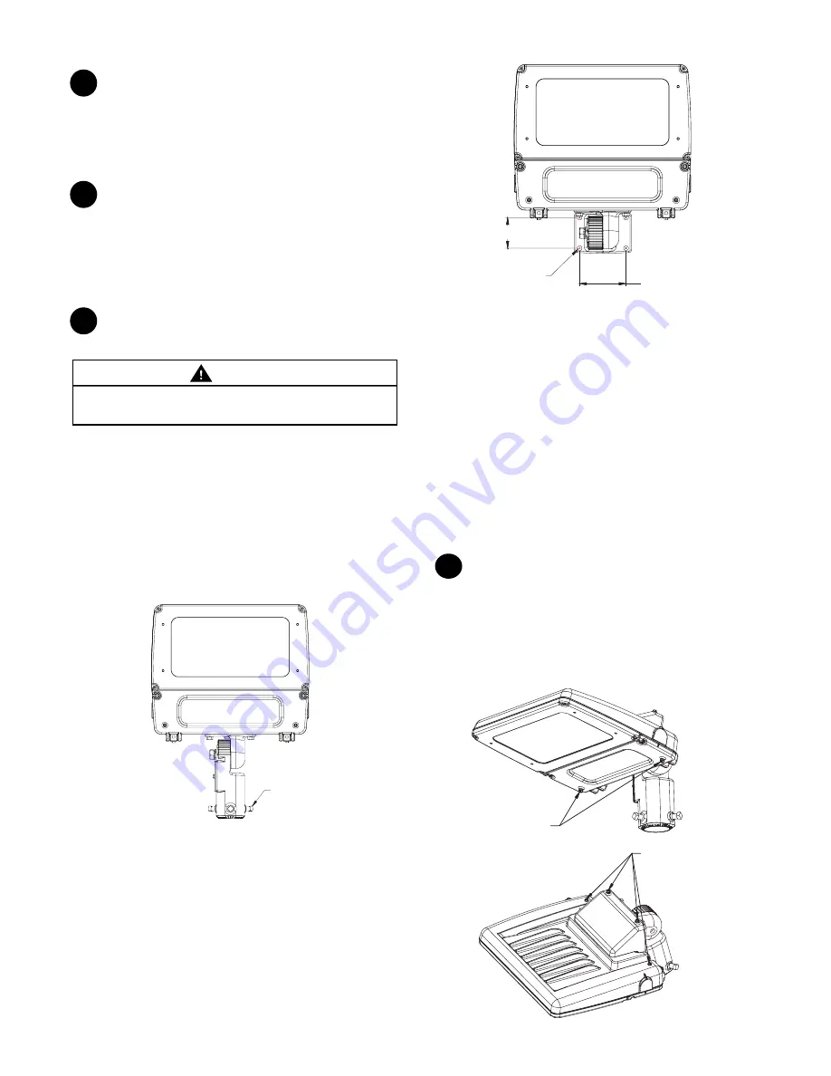
2. Wall Mounted Units:
The wall mounting plate
is provided with four .438-inch clearance holes spaced
4.375(H) x 2.875(V) inches for mounting. Do no mount
the unit such that the hinge side of door is higher than
the latch side of door.
FIGURE 2
2.875 in.
4 Holes
.4387 in.
4.375 in.
AIMING
3
1. Downward Aiming:
On any orientations where
the glass is facing downward, remove the two power
door drain hole screws.
IMPORTANT: make sure all four rear drain holes are in
place on downward orientations
FIGURE 3
Remove Drain Screw
for downward position
Drain Screw remain
for downward position