GE C2S995SEL Скачать руководство пользователя страница 4

4

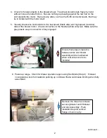
If holes aren’t aligning easily, 

consider leaving out the two screws 
indicated.  Driving these screws 
under tension may deform ducting 
and cause blower to bind.

11. Transfer the sensor circuit board from the defective blower to the replacement blower.  

Connect the sensor circuit board and connect wire terminals to motor tabs.  

Carefully 

work blower assembly into place

and attach to duct by replacing the hex-head screws 

in the order indicated in the photo above.

12. Power up unit.  Check for blower operation as per Step 2.   

DISCONNECT POWER.

13. Replace:

Hex-head screws in side panel and the Phillips screws in rear splash guard

Motor spill guard

Maintop

Vent trim

RJ45 connector to square hole of rear wire cover

Backguard complement strip and rear wire cover

Rear spacer-to-wall trim

Top burners and grates.

Power unit and check for cooling blower operation one more time per Step 2.   Start a self-

clean cycle and listen for rattles with fan operating at high speed, then cancel self-clean 
operation. 

Содержание C2S995SEL

Страница 1: ...al Mode Press 1 to display stored faults Fault code F350 or F352 will likely be displayed This indicates the ERC has detected that the cooling fan blower wheel is not turning or turning too slowly 2 Enter the ERC s Test Mode by pressing and holding 1 and Bake for three seconds Pulse the cooling blower at low speed by pressing 3 If blower wheel which is visible through the vent trim at rear of main...

Страница 2: ...on Be sure nothing is pressing against the red hub on the end opposite the motor Re route any wires such as the RJ45 connector leads that may lie in contact with the motor shaft 5 Visually check wire connections to the low speed black wire and high speed red wire tabs of the blower motor Check connection to the Neutral white wire tab Make sure the gray plastic six pin connector is fully engaged 6 ...

Страница 3: ...SS WB27X29499 CGS995EEL1DS CGS995SEL1SS WB27X29500 CHS995SEL1SS WB27X29501 8 If line voltage is present the BLOWER TANGENTIAL WB26X29060 will have to be replaced Normally the green sensor circuit board attached to blower motor will be good and can be reused 9 DISCONNECT POWER Loosen the upper rear splash guard Remove the three Hex head screws circled below to loosen side panel 10 Disconnect three ...

Страница 4: ...ng the hex head screws in the order indicated in the photo above 12 Power up unit Check for blower operation as per Step 2 DISCONNECT POWER 13 Replace Hex head screws in side panel and the Phillips screws in rear splash guard Motor spill guard Maintop Vent trim RJ45 connector to square hole of rear wire cover Backguard complement strip and rear wire cover Rear spacer to wall trim Top burners and g...

Отзывы: