For answers to your Monogram,
®
GE Profile
™
or
GE
®
appliance questions, visit our website at
ge.com or call GE Answer Center
®
service,
800.626.2000.
Specification Revised 12/07
221218
You must use the rear filler strip kit shipped with
the range or the optional accessory backguard
when installing these ranges
Note:
Cabinets installed adjacent to slide-in
ranges must have an adhesion spec of at least
194° temperature rating.
Optional Kits for Slide-In Gas Ranges:
(Available at additional cost)
Installation Information:
Before installing, consult
installation instructions packed with product for
current dimensional data.
All GE ranges are equipped with
an Anti-Tip device. The installation
of this device is an important,
required step in the installation
of the range.
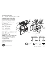
Dimensions and Installation Information (in inches)
C2S980SEMSS
GE Café Free-Standing Dual-Fuel Range
28-1/4*
36
Maintain
at least 6"
from nearest
combustible
surface.
Acceptable
Electrical
Outlet Area
30" Slide-In Range
Dimensions (in inches)
45-1/8
2-1/4
5
6
4-1/2
30
30" Min.
15" Min.
6
30" Slide-in Elec. Range
Aug. 8, 2003 -km
23-3/16
30
30
If you are NOT using the
Filler strip or Backguard:
If you are using the
Filler strip or Backguard:
25
*Wall to front of
closed door handle
on model JSP34.
28" on models
JSP26/JSS26/16.
Note: Range may be placed with 0" clearance (flush) at the back wall and side walls
below countertop if the range side trims above the countertop extend beyond the cabinet
fronts at least 1/4". (Self-clean models only.) Maintain at least 6" distance from nearest
combustible surface.
30
31-1/2
Counter Cutout Dimensions (in inches)
30"
37-1/4"
26-1/4"*
46-3/8"
36-1/4"
+
_
1/4
Product is shipped with 4-prong
plug. Recommended outlet is
a NEMA 14-50R receptacle.
7-1/2
8
9
4
30
3
3
3
2-1/4
2
NOTE: Make
*Dimensions from wall
to front of closed door
handle is 29"
gas connections on
the left side and electrical conections
on the right side of the
cutout opening.
Recommended acceptable
electrical outlet area. Orient
the electrical receptacle so the
length is parallel to the floor.
Wall-Mounted
Recommended area
for through-the-wall
connection of pipe
stub/shut-off valve.
Recommended area for
through-the-floor connection
of pipe stub/shut-off valve.
This area allows
flush installation
to rear wall.


