3
between 5 – 14V
Yellow
Not used
Red
Not used
NOTE:
In off-line mode, the TERM switch (DIP switch 5) must be ‘off’
(up). DIP switches 1 to 4 are not used in off-line mode.
O
PERATING
F
EATURES
Night Light
The reader will be dimly lit when enabled.
Beeper tone
Press and hold the * key while pressing the 1 key to raise the tone
frequency or the 2 key to lower the tone frequency.
P
OWER
U
P
Upon initial power up, the buzzer will sound two beeps indicating that
the internal non-volatile memory is OK. All of the area LEDs may
illuminate indicating that the system is armed. All areas must be
disarmed in order to enable access to the installer programming
menu options.
T
ROUBLESHOOTING
General Faults
No LED display or keypad backlight:
•
Verify the +13.8 and 0V wire connections on both the RAS and
the power supply.
•
Verify power output on the control panel, 4-door controller, or
external power supply.
All three status LEDs are flashing:
•
Verify the D+ and D- wire connections (may be reversed or
open circuit).
•
Verify the address DIP switches of the RAS are set to the
proper address.
•
Verify that the control panel or 4-door controller is polling the
RAS address.
The RAS does not respond to a Smart Card:
•
The RAS may not be programmed correctly or card beep and
LED flash may be disabled. Refer Programming for details.
•
The Smart Card may not be programmed for use with the
particular system.
RX and TX LED Indications
RX and TX LEDs are provided on the circuit board to assist in fault
diagnosis and are visible when the rear plastic cover is removed.
Rx
The yellow Rx LED flashes to indicate polling data is being
received on the system bus from the panel. If the LED does
not flash, the control panel is not operational or the bus is
faulty (usually cabling).
Tx
The red Tx LED flashes to indicate the RAS is replying to
polling from the control panel. If the Rx LED flashes but the
Tx LED does not, the RAS is not programmed to be polled
in the control panel or is addressed incorrectly
.
C
ONFIGURING THE
ATS 1197 RAS
To Configure the RAS:
•
Press 19 [ENTER] followed by * 3 [ENTER.
•
Type the requred RAS address (2 – 16). followed by [ENTER].
•
Select the RAS.
•
Disable the option ’LCD Arming Station’.
•
Enable the option ‘3 LED RAS’.
P
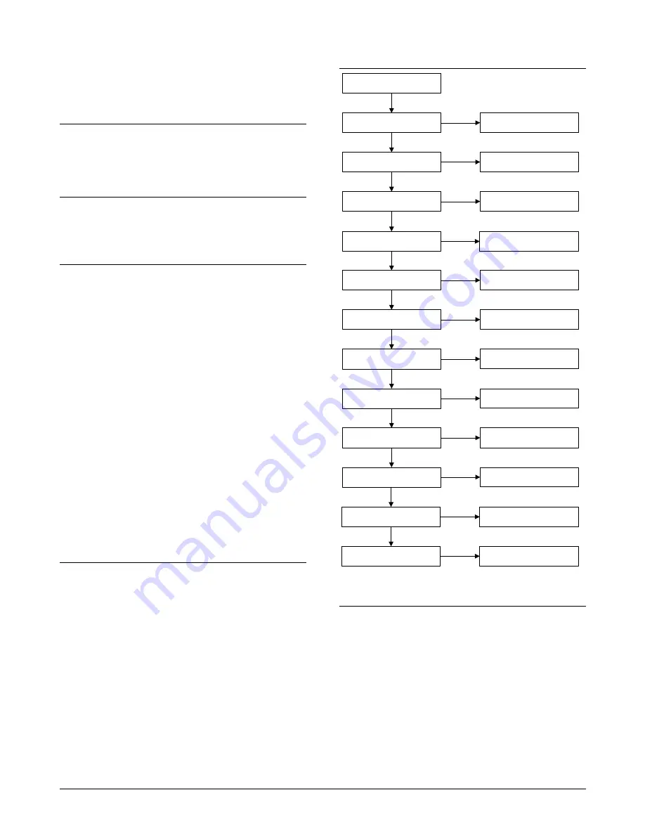
ROGRAMMING MAP
2-LEDs off-line
0-Exit, Menu:
GE Security, RAS1197.V01
0-EXIT, Menu:
Two wire Led Control
*-Change, #-Exit
3-Valid Card Flash
0-Exit, Menu:
Enabled
*-Change, #-Exit
4-Night Light
0-Exit, Menu:
Enabled
*-Change, #-Exit
6-Card Beep
0-Exit, Menu:
Enabled
*-Yes, #-No
7-Watch Dog
0-Exit, Menu:
Disabled
*-Change, #-Exit
8-O/C Output
0-Exit, Menu:
Door Output
*-Change, #-Exit
9-Option Card
0-Exit, Menu:
Enabled
*-Change, #-Exit
10-RTE (Egress)
0-Exit, Menu:
RTE Disabled
*-Change, #-Exit
11-Factory Defaults
0-Exit, Menu:
Set Defaults?
*-Yes, #-No
5-Protocol Options
0-Exit, Menu:
Wiegand
*-Change, #-Exit
13-Last Card
0-Exit, Menu:
00,00,00,00,00,00
#-Exit
16-Security Mode
0-Exit, Menu:
Un-Secured Mode
*-Change, #-Exit
Note:
Reserved menus are not shown
P
ROGRAMMING OPTIONS
The ATS1197 provides for a menu through which a number of
options can be set.
To enter the programming menu for the ATS1197:
•
Enter menu 28 of the Control Panel installer menu.
•
Press 2[ENTER] followed by the RAS address selected and
[ENTER] to enter the RAS menu. The display now shows “GE
Security, RAS1197” followed by the version number.
•
Press [ENTER] to proceed to the menu or press the menu
number followed by [ENTER] to go to a menu item directly.
Menu 1, 12, 14 and 15 are reserved menu’s.
Menu 2, LEDs off-line
Select either two-wire (default) or one-wire LED control.
For two-wire LED control:
•
The brown wire controls LED 1 red (Arm). Wire grounded: LED
1 red on, wire open or at +5 V to +14 V: LED 1 off.


