


Door/Window & Long Life Door/Window Sensors
Installation Instructions
2
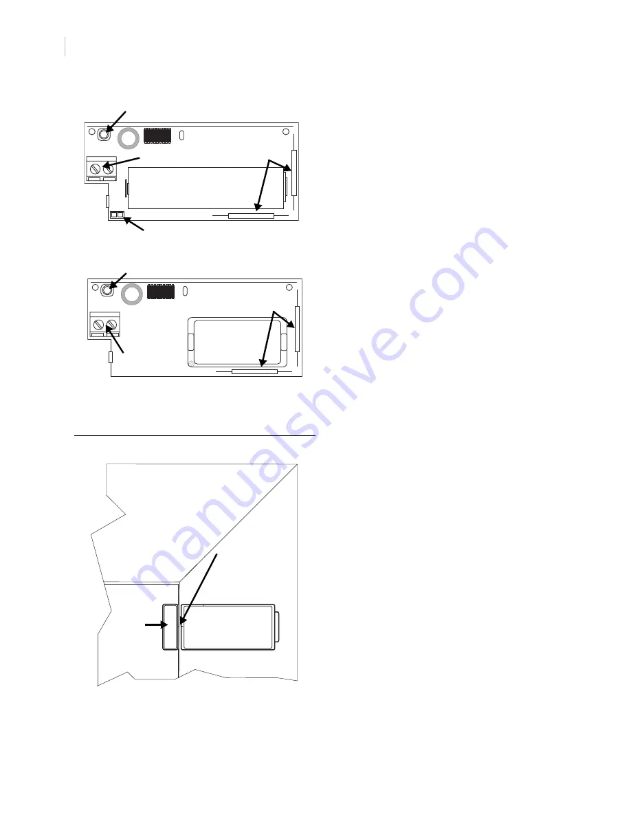
Fig 2. Continued from Page 1
5.
Mount the sensor base. Next, remove the magnet from the
base and mount it no more than 3/8” from the sensor base
(see Figure 3).
Figure 3.
Sensor Base and Magnet Mounted on a Door and Door Frame
Note:
Mount the magnet so that it does not interfere with door or
window openings. Do not use double-sided tape or other
adhesive products.
6.
Connect the circuit board to the base.
7.
Replace the sensor cover.
Connecting External Switches
Door and window sensors can be connected to normally open
(close on alarm) or normally closed (open on alarm) external
switches. For normally open switches, wire multiple sensors in
parallel; for normally closed switches, wire multiple sensors in
series.
Do not use both a built-in reed switch and an external switch on
the same door/window sensor. For high-security installations,
remove
both
reed switches when external switches are connected
to sensor terminals.
Note:
For UL-listed installations, use only a normally closed
configuration.
Materials Needed
• Sealed, external reed switches with a minimum 250 mS
open or close on alarm.
• Stranded, 22-gauge wire.
Installation Guidelines
• Do not use solid-core wire or mechanical switches.
• For remote device connections, do not use a sensor’s built-
in reed switches.
• Do not connect fast pulse devices such as a Window Bug to
a door or window sensor.
• Do not exceed a wire length of 25 feet for 22-gauge,
stranded wire runs. For UL-listed installations, do not
exceed a wire length of three feet between a sensor and
external device.
• Do not exceed a length of six feet for untwisted wire pairs.
• Connect up to five switches and one alarm screen to a door/
window sensor.
• Do not route wire runs parallel to other electrical wires. If a
parellel wire run cannot be avoided, ensure a minimum
distance of 18” exists between the nearest electrical wiring.
• When necessary, cross electrical wires at a 90° angle.
Programming
The following provides a general guideline for programming a
door/window sensor into panel memory. Refer to specific panel
Installation Instructions
for complete programming details.
1.
Set panel to
Program Mode.
2.
Enter the
Learn Sensors
menu. Next, select the appropriate
sensor group and number assignments.
3.
Set external switches to
Alarm
(open for normally closed
circuits; closed for normally open circuits).
4.
Remove sensor cover. The sensor tamper switch trips.
5.
Exit
Program Mode.
6.
Replace sensor cover.
Testing
The following provides a general guideline for testing a door/
window sensor. Refer to the specific panel
Installation Instruc-
tions
for complete testing details.
1.
Set panel to
Sensor Test Mode.
2.
Trip the sensor. Listen for interior siren beeps to determine
appropriate responses (refer to the panel
Installation
Instructions
).
The Long Life Door/Window Sensor has a built-in power saving
feature that automatically turns on when a sensor is tripped two
or more times within a four minute period.
When the power saving feature is on and a sensor is tripped, the
sensor transmits only half of the regular data rounds.
Tamper Switch
3.6V Battery
Reed Switch
Jumper
Terminals
60-641 (New)
Tamper Switch
Terminals
3.6V Battery
Reed Switch
60-632 (New)
Alignment Marks
Magnet
Sensor
Door
Door Frame