Connecting the TruVision NVR 40
16
TruVision NVR 40 User Manual
Basic setup
To start the TruVision NVR 40 unit and connect to the network, follow this procedure:
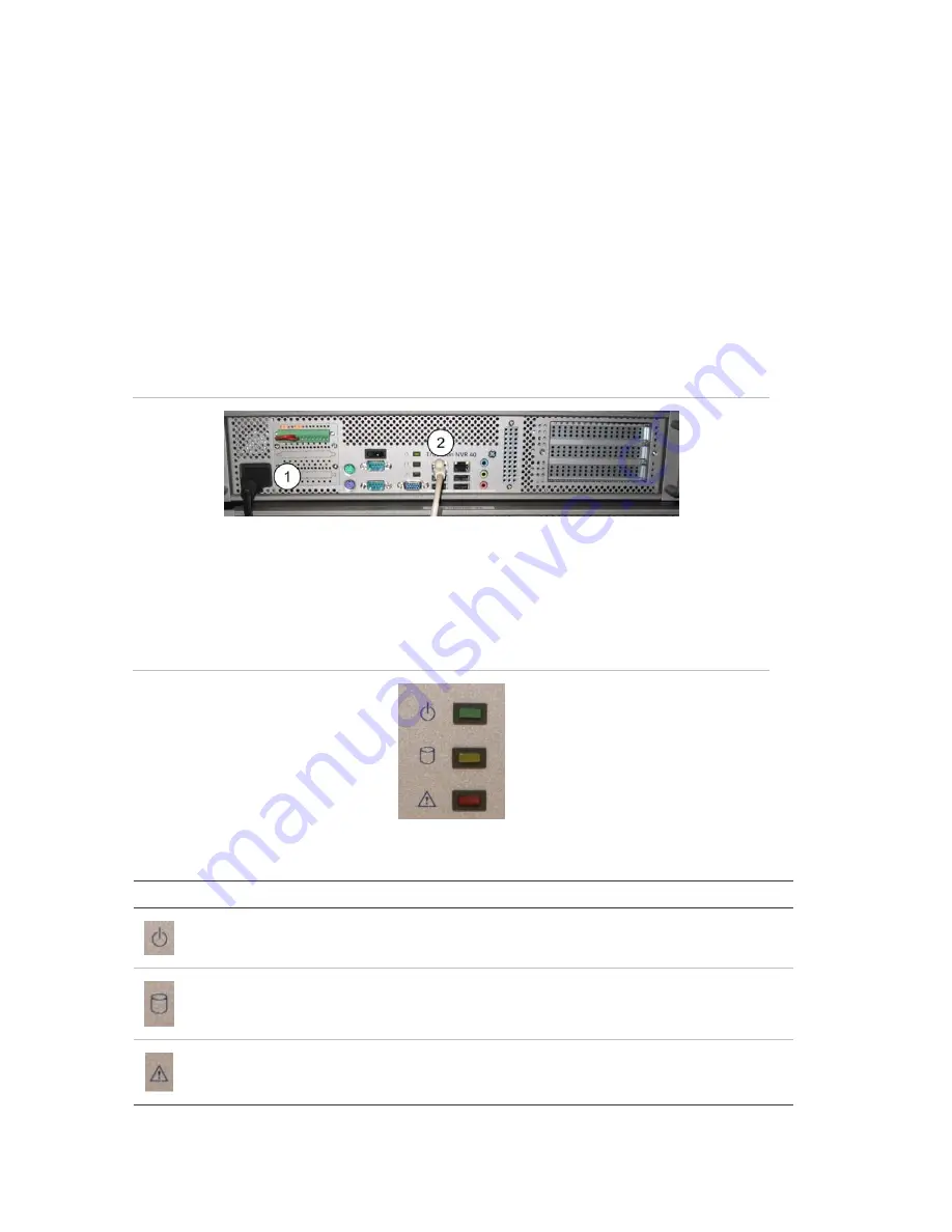
1. Attach the power cord to the unit. See Figure 9, item 1
2. Attach the Ethernet cable to the Ethernet port. See Figure 9, item 2.
3. Press the power button on the front panel, to turn on the unit. See Figure 7.
4. The topmost LED on the front panel indicates whether AC mains power is present,
constant green indicates when the power is on. See Figure 10 below.
5. You are now ready to configure the TruVision NVR 40 through its Web server
using a host computer. See Figure 11 on page 18.
Figure 9: NVR 40 basic setup connections
Front panel LEDs
There are 3 different LED indicators on the front panel of the unit.
Figure 10: Front panel LEDs
Table 2: Front panel LEDs
Icon LED
Description
Power status
This LED indicates when the unit is turned on. Constant green
indicates power on.
Storage status/activity
This LED monitors the status of the storage in the system.
VOS (video operating
system) identification LED
This LED indicates when the embedded software (VisioWave Security
Service) has detected an abnormal condition or a failure.*
*
In case of storage failure (LED is constant red), contact technical support.


