background image

19

Each generator is shipped with a set of identical keys. These 
keys fit in the lock on the front removable panel. The roof 
must be unlocked in order for it to open.

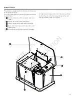
access Panels

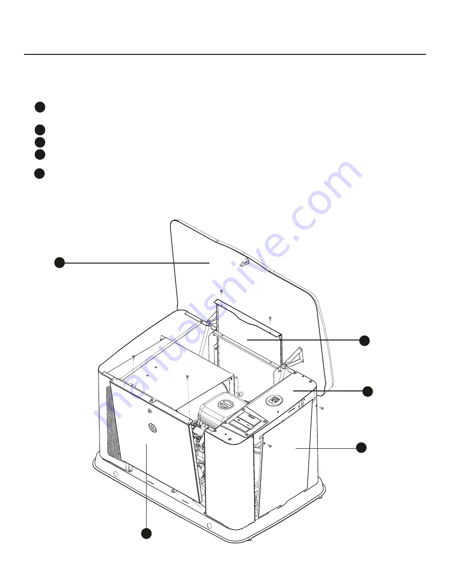
The generator is equipped with an enclosure that has several 
access panels, as shown. 
The access panels and the components located behind them 
are listed below:
 

A - Roof (Control Panel, air filter, oil dipstick, and circuit 

breaker)


B - Front Access Panel (oil drain and oil filter)


D - Battery Panel (battery and generator data label)


E - Rear Access Panel (fuel regulator, fuel selector, and 

engine starter)


F - Control Panel Cover (field wiring and control wires) 

B

A

A

B

c

C

D

E

D

E

B

NOT 

for 

REPRODUCTION

Содержание 20 kW Home

Страница 1: ...1 GE Home Generator Systems Home Generator System Installation and Start Up Manual N O T f o r R E P R O D U C T I O N ...

Страница 2: ...ng refrigeration systems and communication systems that when stopped during any power outage could cause discomfort or inconvenience Save these original instructions for future reference This generator requires professional installation before use The installer should follow the instructions completely Where to Find Us You never have to look far to find support and service for your generator For q...

Страница 3: ...ts and Testing16 Electrical and Fuel Inlet Locations 17 Lifting the Generator 18 Concrete Anchoring of Unit 18 Access Panels 19 The Gaseous Fuel System 21 Fuel Factors 22 System Connectors 25 Generator AC Connection System 26 Grounding the Generator 26 Power Connections from Generator to Transfer Switch 27 System Control Board 28 Menu 29 General Set Up Screen 30 Control Panel Prompts 31 Advanced S...

Страница 4: ...and related accessories contain chemicals known to the State of California to cause cancer birth defects or other reproductive harm Wash hands after handling WARNING Running engine gives off carbon monoxide an odorless colorless poison gas Breathing carbon monoxide could result in death serious injury headache fatigue dizziness vomiting confusion seizures nausea or fainting Operate this product ON...

Страница 5: ... electric utility workers due to backfeed of electrical energy DO NOT touch bare wires or bare receptacles DO NOT use generator with electrical cords which are worn frayed bare or otherwise damaged DO NOT handle generator or electrical cords while standing in water while barefoot or while hands or feet are wet If you must work around a unit while it is operating stand on an insulated dry surface t...

Страница 6: ...ases fuel leakage oil leakage etc If connected devices overheat turn them off and disconnect them from generator Shut off generator and contanct an authorized deaker if electrical output is lost equipment sparks smokes or emits flames unit vibrates excessively unit makes unusual noises WARNING Exhaust heat gases could ignite combustibles or structures resulting in death serious injury and or prope...

Страница 7: ...ential to maintain life where current interruption of the normal supply would produce serious life safety or health hazards Legally Required standby generator systems are intended to automatically supply power to selected loads in the event of failure of the normal source which could create hazards or hamper rescue or fire fighting operations Every effort has been made to ensure that information i...

Страница 8: ...ing battery Connecting wire and conduit Fuel supply valves plumbing Crane lifting straps chains or cables Two 60 lengths of 3 4 nominal minimum scheduled 40 steel pipe NOT conduit Torque screwdriver 5 to 50 inch pound range Voltage frequency meter Two 2 AA batteries for remote wireless monitor Shipment Contents Avoid damage from dropping bumping collision etc Store and unpack carton with the prope...

Страница 9: ...ring is rated for 600V See Transfer Switch Communication Dipswitches in most transfer switches must be set to correspond to the wattage of the generator See Transfer Switch Operator Installation Manual Operation Cold weather kit is installed in temperatures below 40 F 5 C See Cold Weather Kit Correct battery type is installed and fully charged See Final Installation Considerations Generator engine...

Страница 10: ...10 Intentionally Left Blank N O T f o r R E P R O D U C T I O N ...

Страница 11: ...ury headache fatigue dizziness vomiting confusion seizures nausea or fainting Operate this product ONLY outdoors in an area that will not accumulate deadly exhaust gas Keep exhaust gas away from any windows doors ventilation intakes soffit vents crawl spaces open garage doors or other openings that can allow exhaust gas to enter inside or be drawn into a potentially occupied building or structure ...

Страница 12: ...ating condition in your home Carbon monoxide detector s A MUST be installed and maintained indoors according to the manufacturer s instructions recommendations A CO monitor is an electronic device that detects hazardous levels of CO When there is a buildup of CO the monitor will alert the occupants by flashing visual indicator light and alarm Smoke alarms cannot detect CO gas Your neighbor s home ...

Страница 13: ...andby generator exhaust away from or parallel to the building or structure DO NOT direct the generator exhaust towards a potentially occupied building structure windows doors ventilation intakes soffit vents crawl spaces open garage doors or other openings where exhaust gas could accumulate and enter inside or be drawn into a potentially occupied building or structure ENGINE EXHAUST STANDBY GENERA...

Страница 14: ...ng or trees Standby Weatherproof enclosure must have a minimum of 18 inches 45 7 cm clearance from any structures with or without a fire rating NOTICE DO NOT place weatherproof enclosure under a deck or other type of covered structure that may confine airflow Vertical Clearances Legend for Generator Locations to reduce the risk of fire WARNING Exhaust heat gases could ignite combustibles or struct...

Страница 15: ...enclosure under a deck or other type of covered structure that may confine airflow 18 in 45 7 cm min Standby Exhaust Direction A A B Standby Exhaust Direction A A B 5 ft 1 5 m min Standby Exhaust Direction 5 ft 1 5 m A A B Standby Exhaust Direction A B Generator Installations 5 ft 1 5 m 5 ft 1 5 m min 18 in 45 7 cm min 5 ft 1 5 m 5 ft 1 5 m min 18 in 45 7 cm min 5 ft 1 5 m D D D D D D D Standby We...

Страница 16: ...ed completely of non combustible materials and full scale fire tests have been conducted to demonstrate that a fire within the enclosure will not ignite combustible materials outside the enclosure National Fire Protection Association NFPA Standard NFPA 37 Requirements and Testing Place the standby generator in a prepared location that is flat and has provisions for water drainage Install the stand...

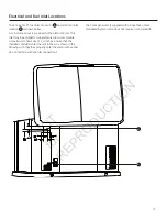
Страница 17: ...larged or supplemented to accommodate a maximum conduit size of 1 inches Ensure that the installed conduit s enter the unit in the zone shown in the drawing such that they properly enter the electrical box and do not interfere with the fully opened roof A B The home generator is supplied with a base that unless mandated by local code does not require a concrete slab N O T f o r R E P R O D U C T I...

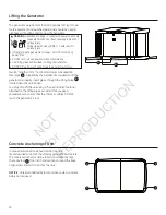
Страница 18: ...ltage Contact with power lines could cause electric shock or burn resulting in death or serious injury Lifting Hazard Heavy Object Could result in serious injury If lifting or hoisting equipment is used DO NOT contact any power lines DO NOT lift or move generator without assistance Use lifting pipes as described in Lifting the Generator DO NOT lift unit by roof as damage to generator will occur In...

Страница 19: ...al access panels as shown The access panels and the components located behind them are listed below A Roof Control Panel air filter oil dipstick and circuit breaker B Front Access Panel oil drain and oil filter D Battery Panel battery and generator data label E Rear Access Panel fuel regulator fuel selector and engine starter F Control Panel Cover field wiring and control wires B A A B C C D E D E...

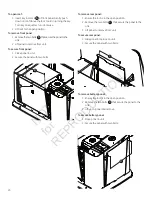
Страница 20: ...re the panel with two bolts To remove rear panel 1 Ensure the roof is in the open position 2 Remove the two bolts that secure the panel to the unit 3 Lift panel to remove from unit To secure rear panel 1 Slide panel into place on unit 2 Secure the panel with two bolts To remove battery panel 1 Ensure the roof is in the open position 2 Remove the two bolts that secure the panel to the unit 3 Lift u...

Страница 21: ...tion shall be provided downstream to permit removal of standby A manometer port should be provided D A digital manometer P N 19495 is available at your Briggs Stratton service center When the initial test runs are completed the manometer is removed and the port is plugged The manometer port permits temporary installation of a manometer to ensure that the engine receives the correct fuel pressure t...

Страница 22: ...An important consideration affecting the entire installation is the type of fuel used by your generator The system was factory tested and adjusted using natural gas but can be converted to use LP vapor For proper engine function factors that are inherent to each of these fuels your location and the duration of possible utility interruptions are important considerations in the following fuel guidel...

Страница 23: ...e lock to aid in turning the key Turn key one quarter turn clockwise 2 Lift roof to the open position 3 Press the control board OFF button 4 Remove 15 Amp fuse from control panel 5 Remove the rear panel A 6 Locate the fuel selector switch A located on top of the fuel regulator B Using a 5 mm Allen wrench turn the selector switch to either LP or NG 7 Reinstall the rear panel 8 Reinstall 15 Amp fuse...

Страница 24: ...id 1 56 1 5 1 42 BTU Hr 140000 135000 127500 Exercise Cu Ft Hr 40 40 40 Gal Hr liquid 1 11 1 11 1 11 BTU Hr 100000 100000 100000 Recommended Energy Content of Fuel Natural Gas Propane LP Vapor Heating Value BTU per gallon liquid gross BTU per Cubic feet vapor N A 1 000 91 547 2 500 Natural Gas 20 kW 18 kW 17 kW 14 4 kW 15kW 13 5 kW Full Load Cu Ft Hr 260 248 240 BTU Hr 260000 248000 240000 3 4 Loa...

Страница 25: ...al Block Used to connect signal wires to the control board Connect only one wire per terminal F Power Connection Line 1 and Line 2 Power connection to transfer switch G Neutral and Ground Connection Connect to transfer switch neutral and ground For power output connection Line 1 Line 2 Neutral and Ground refer to the following table Power output connections minimum 300V 75 C 15 kW 17 kW 20 kW 6AWG...

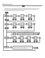
Страница 26: ...h the generator 33 240V 11 22 44 120V 120V 11 22 44 0 Neutral Power Winding Circuit Breaker Line 1 Neutral To Transfer Switch Line 2 Ground Circuit Breaker Grounding the Generator From Alternator Power Windings The home generator must be installed as part of a system that includes a listed transfer switch with neutral to ground bonding at the transfer switch in accordance with installation instruc...

Страница 27: ... 26 for further information Transfer Switch Communication Using installer supplied 18 AWG twisted pair conductors no greater than 200 ft in length connect Tx Rx and Tx Rx GND from the generator terminal block A to T R and GND on the transfer switch control board B B A Generator Power Connection Using installer supplied minimum 300V wires and the table located on page 25 connect generator power out...

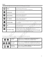
Страница 28: ... prevents unit from starting and resets any detected faults OFF must be pressed and held for more than 5 seconds in order to reset service codes MANUAL Used to manually start the generator AUTO LED LED will light when unit is placed into Auto mode LED will blink if exercise cycle is not set or set to OFF D 15 Amp Fuse Protects the home generator DC control circuits If the fuse has blown melted ope...

Страница 29: ...NSED THE SYSTEM WILL START THE GENERATOR WHEN UTILITY POWER IS RESTORED AUTO LETS THE ENGINE STABILIZE INTERNAL TEMPERATURES SHUTS OFF THE GENERA TOR AND WAITS FOR THE NEXT UTILITY POWER OUTAGE ok ok ok ok ok ok ok GENERAL SET UP PRESS AND HOLD ARROW LEFT AND ARROW RIGHT FOR THREE SECONDS TO ENTER THE PROGRAM MODE ADVANCED SETTINGS PRESS AND HOLD ARROW LEFT ARROW RIGHT AND ESC FOR THREE SECONDS TO...

Страница 30: ... FLASHING ok ok ok or or or DAY FLASHING YEAR FLASHING SET TIME ok HOURS FLASHING ok ok ok or or MIN FLASHING SET EXERCISE CYCLE ok or AM PM FLASHING HOURS FLASHING ok or ok or MIN FLASHING ok DAY OF WEEK FLASHING or AM PM FLASHING ok or or or EVENT LOG ok Display will scroll last service code event date time and temperature of when the event occured ok or OFF If set to OFF display will read EXERC...

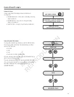
Страница 31: ... RUN TIME DATE or or or TIME EXERCISE CYCLE GENERATOR ON When Generator Running Auto Mode GENERATOR READY or SERVICE CODE DESCRIPTION When Generator NOT Running Auto Mode MENU ok General System Parameters To view general system parameters press the MENU button The following will scroll across the digital display and then move to the next item Run time Date Time Exercise Cycle date and start time T...

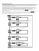
Страница 32: ...n should be taken when working in the Advanced Settings menu Exercise caution when selecting and verifying parameters for the generator and region where the generator is being operated Confirm all settings before operating the generator for the first time For advanced menu items press and hold the left arrow right arrow and escape key for 3 seconds Follow the prompts as outlined below NOTICE In th...

Страница 33: ...cranking amps 630 CCA cold cranking amps Construction Wet lead acid Wet lead acid Terminal Type Top post type battery Top post type battery Dimensions MAX BCI size 26 BCI size 75 Install the battery as described in Servicing the Battery in the Maintenance section of the operator s manual Always make sure the NEGATIVE cable is connected last and that the red POSITIVE terminal insulator is fully in ...

Страница 34: ...lines be purged This may cause the engine to run roughly for a few minutes 6 Listen for unusual noises vibration or other indications of abnormal operation Check for oil leaks while engine runs 7 Let engine warm up for about 5 minutes to allow internal temperatures to stabilize 8 Check generator output at load side of circuit breaker Voltage should be 225 250 Volts frequency should be 59 0 61 0 Hz...

Страница 35: ...ons may be related to an electronic governing system issue Engine Does Not Start Over Speed Under Frequency Unstable No Load Engine Control While trouble shooting any of these conditions a verification of the electronic governor system can be initiated through the control panel advanced menu options Electronic Governor Check Electronic Governing Check The generator has an electronic governing chec...

Страница 36: ...during the exercise cycle unless an utility power outage occurs The generator will only enter the exercise cycle if the unit is in the AUTO mode and this exact procedure is followed To set the exercise timer NOTICE The generator is set with a default exercise cycle setting of Tuesday at 2 00 P M Central Time To change the cycle setting proceed to the following steps 1 Choose the day and time you w...

Страница 37: ...om antenna post and remove from antenna wire 5 Route antenna wire D from the top side of the roof through the hole in the roof where the plug was removed 6 Replace flange nut on wire Ensure the wire is routed through the washer end 7 Secure antenna to roof with the flange nut 8 Locate wire connector C coming from control panel and connect to the wire coming from antenna 9 Route wire and secure wit...

Страница 38: ...w battery voltage 2 low fluid level 3 under over voltage 4 engine does not start part 316196 fcc id MCQ XBS2C IC id 1846A XBS2C 5 low frequency 6 engine overspeed 7 high temperature 8 transfer switch of flashes service needed A B C D E F G Compare the illustration below with your monitor to familiarize yourself with these important components Generator Ready A Green LED Generator Power B Green LED...

Страница 39: ...itor will display the current state The monitor will try to link for 1 minute This step can only be completed when the generator is in Linking Mode 6 Once the link has been confirmed press the OK button on the generator control panel to exit or the control board will turn off linking after 5 minutes The generator will now communicate with the wireless monitor NOTICE It may take up to 1 minute for ...

Страница 40: ...example when Low Frequency scrolls across the control board the red LED will flash 5 times with a 3 second pause between series of blinks until it is reset or the condition is corrected When the red LED is lit contact your nearest authorized service dealer NOTICE None of the conditions on the display unit can be cleared at the wireless monitor All alerts must be cleared at the generator control pa...

Страница 41: ...41 NOTES N O T f o r R E P R O D U C T I O N ...

Страница 42: ...42 NOTES N O T f o r R E P R O D U C T I O N ...

Страница 43: ...43 Schematic Diagram Schematic Wiring Diagrams N O T f o r R E P R O D U C T I O N ...

Страница 44: ...license by Briggs Stratton Power Products Group LLC Copyright 2012 All rights reserved No part of this material may be reproduced or transmitted in any form without the express written permission of Briggs Stratton Power Products Group LLC N O T f o r R E P R O D U C T I O N ...

Отзывы: