background image

Field replaceable units: 

Replace main unit parts

7-40

Dash 3000/4000/5000

2000966-542D

Replace NBP pump assembly

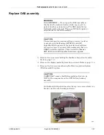
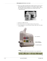
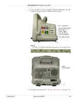
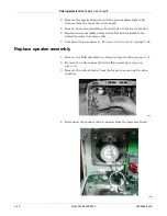
1. Remove the DAS assembly according to steps starting on page

 7-37

.

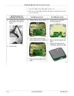
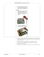
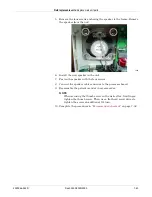
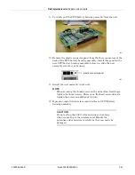
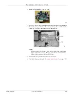
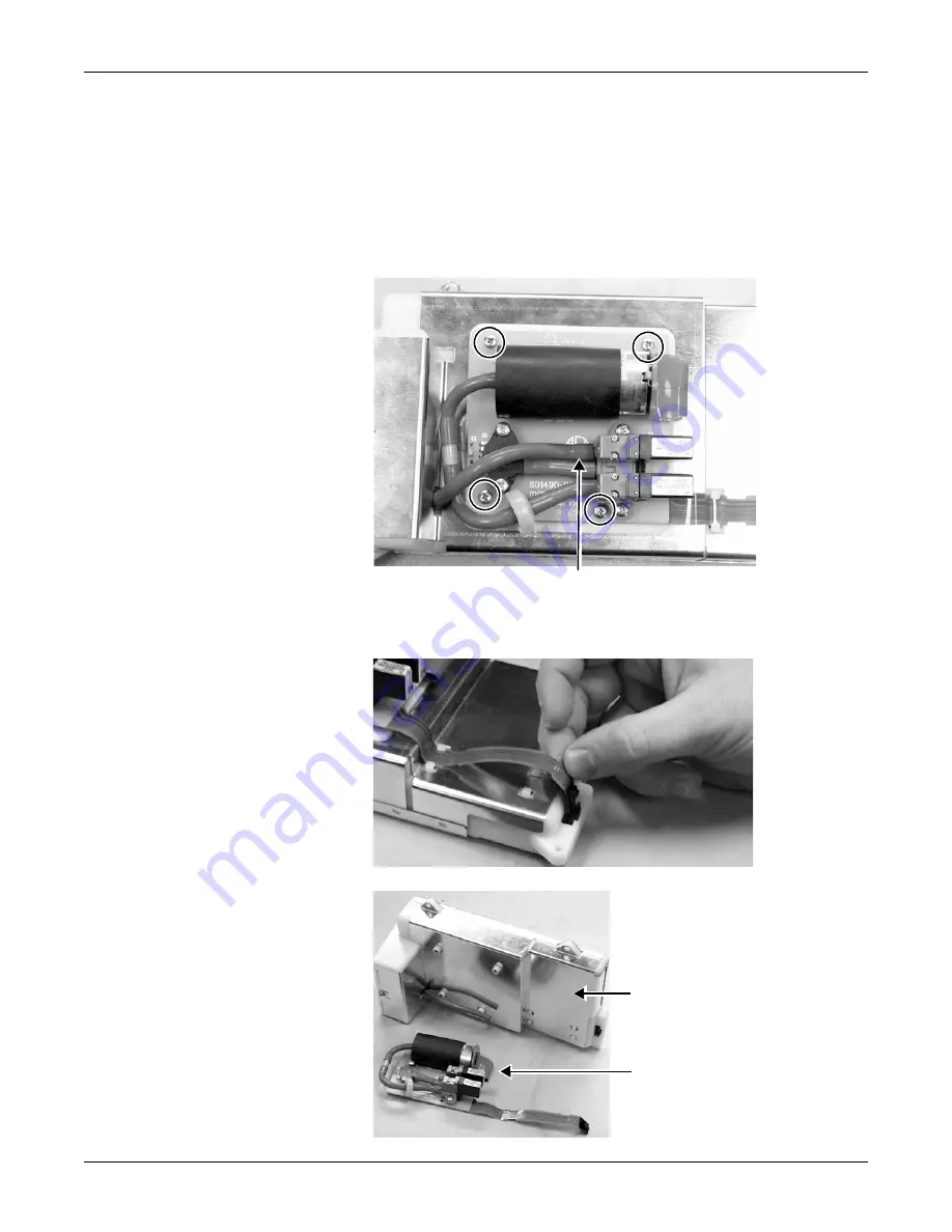
2. Remove the four screws and remove the NBP assembly from the 

cover of the DAS assembly.

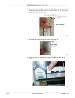
3. Disconnect the tube from the inner solenoid going into the NBP 

assembly.

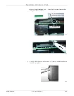
4. Using a small, flat-blade screwdriver, remove the connector from the 

NBP assembly to the DAS assembly.

Disconnect this end of the tube.

Remove four 
screws.

570A

527A

DAS assembly FRU

NBP pump assembly FRU

526A

Содержание 001C 051D 003A

Страница 1: ...GE Healthcare Dash 3000 4000 5000 Patient Monitor Service Manual Software Version 7 Dash 3000 4000 5000 English 2023909 014 CD 2023896 104 paper 2011 2013 General Electric Company All rights reserved ...

Страница 2: ...eshooting instructions found in the service manual you received with your patient monitor NOTE The 802 11 a b g wireless feature is only compatible with Dash 3000 4000 5000 patient monitors with software version 7 or later NOTE The Dash Port 2 docking station with version 2 1 or later software is only compatible with the Dash 3000 4000 5000 patient monitor with version 7 2 or later software NOTE F...

Страница 3: ... Equipment identification 1 9 2 Equipment overview 2 1 Components 2 2 Monitoring system 2 2 Patient monitor 2 2 Controls and indicators 2 6 Exchangeable or compatible battery packs 2 9 Optional components 2 10 Optional remote control 2 13 Software packages and software options 2 14 Software packages 2 14 Software options 2 14 Ethernet communication 2 15 About Ethernet 2 15 Twisted pair 2 15 Networ...

Страница 4: ...ctions 3 5 Power up 3 7 Configure 3 7 Dash installation checkout procedure 3 8 4 Configuration 4 1 Before you begin 4 2 Service menus 4 3 Boot Loader Service Menu 4 4 Main menu service mode 4 5 Procedures 4 9 Set print locations 4 10 Service Mode settings 4 11 Set Unit Name 4 11 Set Bed Number 4 11 Patient Monitor Type 4 12 Admit Menu 4 13 Confirm or configure wireless LAN 4 14 Boot Code settings ...

Страница 5: ... or results of improper cleaning products and processes 5 5 Cleaning products to avoid 5 5 Storage 5 5 Clean the print head 5 6 Cleaning disinfecting and storing GE ECG cables and leadwires 5 7 Cleaning and disinfecting 5 7 Sterilization 5 8 Cautions 5 8 Storage 5 8 Improper cleaning products and processes impact or results 5 8 Cleaning products to avoid 5 9 Cleaning other applied parts 5 9 Batter...

Страница 6: ...ry Fuel Gauge Icon 6 8 Writer or printer 6 9 External 6 9 Internal 6 9 No waveform at central station 6 10 Monitor defaults transfer 6 11 Storing monitor defaults 6 11 Copying stored monitor defaults 6 11 Change internet address 6 12 Review errors 6 13 View output or input errors 6 13 Useful error data 6 14 Get error logs 6 16 Get logs via PC using netUpdate 6 16 Get logs via CIC 6 21 Get logs via...

Страница 7: ... or Trim Knob control 7 30 Replace display components without LCD 7 31 Replace main unit parts 7 34 Replace wireless card 7 34 Replace DAS assembly 7 37 Replace NBP pump assembly 7 40 Replace writer assembly or writer flex 7 41 Replace speaker assembly 7 42 Replace CPU battery housing assembly 7 44 Replace power supply assembly 7 48 Replace battery door 7 50 Replace foot 7 50 Replace writer cover ...

Страница 8: ...8 25 Temperature tests 8 26 Cardiac output tests option 8 27 Invasive blood pressure tests option 8 27 Pulse oximetry tests for GE Ohmeda SPO2 oximeter 8 30 Pulse oximetry tests for Masimo SET SPO2 8 32 Pulse oximetry tests for Nellcor OxiMax SPO2 8 33 Noninvasive blood pressure tests 8 35 NBP calibration 8 37 Analog output and defibrillator synchronization tests 8 40 End tidal CO2 test option 8 4...

Страница 9: ... B 2 Network infrastructure compatibility B 3 Compatible wireless network infrastructures B 3 Problem No waveforms or parameters are displayed at the CIC Pro center B 5 C Network disclosure to facilitate network risk management C 1 Purpose and scope C 2 Purpose for the Dash patient monitor connection to network C 2 Dash patient monitor network interface technical specifications C 2 Network informa...

Страница 10: ...viii Dash 3000 4000 5000 2000966 542D ...

Страница 11: ...2000966 542D Dash 3000 4000 5000 1 1 1 Introduction ...

Страница 12: ...dentifies additional sources of relevant information and technical assistance See the operator s manual for the instructions necessary to operate the equipment safely in accordance with its function and intended use Intended audience This manual is intended for service representatives and technical personnel who maintain troubleshoot or repair this equipment Ordering manuals A paper copy of this m...

Страница 13: ...nnecting any devices to the equipment that are not recommended in this manual Parts and accessories used must meet the requirements of the applicable IEC 60601 series safety standards and or the system configuration must meet the requirements of the IEC 60601 1 1 medical electrical systems standard Periodically and whenever the integrity of the device is in doubt test all functions The use of acce...

Страница 14: ...ned as a source of potential injury to a person DANGER indicates an imminent hazard which if not avoided will result in death or serious injury WARNING indicates a potential hazard or unsafe practice which if not avoided could result in death or serious injury CAUTION indicates a potential hazard or unsafe practice which if not avoided could result in minor personal injury or product property dama...

Страница 15: ... heart is established The paddles indicate the equipment is defibrillator proof Defibrillator proof type BF equipment type BF equipment is suitable for intentional external and internal application to the patient excluding direct cardiac application Type BF equipment is type B equipment with an F type isolated floating part The paddles indicate the equipment is defibrillator proof Type B equipment...

Страница 16: ...CAN CSA C22 2 NO 601 IEC 60601 1 IEC 60601 2 27 IEC 60601 2 30 IEC 60601 2 34 and IEC 60601 2 49 This symbol indicates that the waste of electrical and electronic equipment must not be disposed as unsorted municipal waste and must be collected separately Please contact an authorized representative of the manufacturer for information concerning the decommissioning of your equipment This product con...

Страница 17: ...afety sign ISO 7010 W005 Warning non ionizing radiation FCC USA only Complies with applicable US government Federal Communications Commission radio frequency interference regulations Manufacturer name and address Device serial number Russia only GOST R certification where XXXX indicates the four digit certification body number determined by product Catalog or orderable part number European authori...

Страница 18: ...l not result in any severe environmental pollution any bodily injury or damage to any assets The unit of the period is Year In order to maintain the declared EFUP the product shall be operated normally according to the instructions and environmental conditions as defined in the product manual and periodic maintenance schedules specified in Product Maintenance Procedures shall be followed strictly ...

Страница 19: ...atisfactory maintenance schedule may cause undue equipment failure and possible health hazards Regular maintenance irrespective of usage is essential to ensure that the equipment will always be functional when required Equipment identification Every GE device has a unique serial number for identification A sample of the information found on a serial number label is shown below Description A produc...

Страница 20: ...Introduction Service information 1 10 Dash 3000 4000 5000 2000966 542D ...

Страница 21: ...2000966 542D Dash 3000 4000 5000 2 1 2 Equipment overview ...

Страница 22: ...Network name they refer to the same GE monitoring network The CARESCAPE Network MC will be referred to as the MC network throughout this document The CARESCAPE Network IX will be referred to as the IX network throughout this document Patient monitor This device is designed to monitor a fixed set of parameters including ECG noninvasive blood pressure impedance respiration SpO2 and temperature Invas...

Страница 23: ...connectors are located on the right side of the patient monitor A Trim Knob control provides single control operation of virtually all patient monitor functions Left side view On the left of the patient monitor you can find the built in writer and the battery compartment Patient cable connectors 002A 925B A B ...

Страница 24: ...tment may be a single plastic door or two silicone doors Name Description A wireless transmitter label Identifies monitors that contain an internal wireless transmitter for network communication B line voltage selector This selector is factory set to match the line voltage rating for your country C speaker The internal speaker provides sound for audible alarms For better sound quality do not block...

Страница 25: ...to connect a monitor to the Unity Network for patient monitoring or for software installation H peripheral expansion port Used for connecting to a Dash Port docking station or other compatible auxiliary devices I AC power connector Provides connection for AC power cable The internal power supply converts the AC current to DC power The monitor is preset at the factory for a specific AC voltage Refe...

Страница 26: ...e surface coating on the viewing side of the filter It also has a scratch resistance surface coating Trim Knob control The Trim Knob control is a 24 position rotary control with a push selection switch Function or power keys Dash 3000 4000 patient monitors Power Print NBP Go Stop Zero All Silence Alarm Admit Dash 5000 patient monitor Power Standby Admit Discharge NBP Go Stop NBP Auto Print Silence...

Страница 27: ... mains power Battery power indicator The indicator lights yellow when the patient monitor is operating on battery power The indicator does not illuminate when the patient monitor has no battery power Battery indicators are located on the front panel of the patient monitor They indicate when battery power is used and the battery charging status Charging status indicators An icon for each battery in...

Страница 28: ... indicators do not illuminate when the patient monitor is not battery powered Neither indicator lights when the patient monitor is operating from both batteries simultaneously e g in a very low battery charge condition when both batteries are joined together in order to sustain operation of the patient monitor Battery capacity gauge On screen capacity gauges indicate the battery s current state of...

Страница 29: ...nly recognize and charge GE recommended batteries Non recommended batteries will run but not charge the Dash patient monitor If battery is labeled GE Approved the battery is compatible NOTE Incompatible batteries display an ERROR message in the Battery Capacity Gauge on the bottom right corner of the patient monitor screen Icon Description Indicates that the monitor is connected to the Local Area ...

Страница 30: ...nents TRAM rac 2A module housing The TRAM rac 2A module housing currently supports the SAM and ICG modules An integral power supply is used to run the TRAM rac 2A and support the needed voltages Dash Port 2 docking station The docking station is a quick mount dismount base for a Dash patient monitor It gives the patient monitor easy connect or disconnect access to AC power CARESCAPE Network a remo...

Страница 31: ...ftware version 5 through version 7 1 with Dash Port 2 software version 2 0 or Dash 3000 4000 5000 patient monitor software version 7 2 or later with Dash Port 2 software version 2 1 or later and Must be within 150 feet of the Dash patient monitor ICG module The ICG module impedance cardiography measures and processes patient hemodynamic data BISx Available in software version 6 or later BISx measu...

Страница 32: ...twork e g Dash 3000 4000 5000 Eagle 4000 and Solar patient monitors Patient monitors with a wireless connection can send and receive patient data via the access points to the CARESCAPE Network NOTE It is recommended that wireless patient monitors that are moved from room to room have their patient monitor type configured as Rover or Rover Combo monitoring To extend the CARESCAPE Network to a hospi...

Страница 33: ... control The optional remote control provides all patient monitor controls on a portable component with a Trim Knob control and allows the user to operate the patient monitor from across the room Eighteen hard keys are configured for adult neonatal or operating room applications 821A ...

Страница 34: ...eatures include the PA insert and wedge algorithms the intra aortic balloon pump algorithm and the thermodilution cardiac output algorithm including predefined computation constants for the catheters of major manufacturers Also included are cardiac and pulmonary calculations Software options Three software options can be purchased separately or in any combination with the software packages and sof...

Страница 35: ...g is used The Dash patient monitor is designed to be used with twisted pair cabling Consult GE when trying to interface with either thick net or thin net cabling The real time GE CARESCAPE Network operates at 10 Mbps half duplex Twisted pair Twisted pair is the most popular cabling because it is easy to install and flexible to work with It uses the star topology with a switch as the hub of the seg...

Страница 36: ...e star segment Typically the switch supports 12 to 48 network devices and may be linked to other switches to form larger networks Segment A network segment is comprised of all devices connected to one or many switches which are in turn connected together to form a larger network The boundaries of the segment are defined by networking equipment that regulate the flow of packets into and out of the ...

Страница 37: ... expansion port Speaker Handle subassembly including the Alarm Light option Thermal printer optional Battery Overall patient monitor block diagram NBP Flex DAS Board Patient Connector Flex Patient Connections DAS Module Display Keypad Backlight Inverter Display Subassembly Display Flex Processor Board Power Supply Board Battery Battery Peripheral Expansion Connector Processor Power Management Suba...

Страница 38: ...itching power supply No AC mains power switch is provided The line voltage range switch must be set to select 115 V or 230 V 90 to 132 VAC or 190 to 264 VAC respectively Data Acquisition System DAS All interfaces to the patient occur through the DAS The ECG function uses a direct connection to the patient therefore it is separately isolated from the other functions except respiration which shares ...

Страница 39: ...ENSOR MOUNTED ON 801368 001 HYBRID LDO REG 5V TO DIGITAL CIRCUITRY ISOLATION BARRIER ISOLATION BARRIER ISOLATION BARRIER DC DC CONVERTER SECONDARY CIRCUITRY DC DC CONVERTER PRIMARY CIRCUITRY DC DC CONVERTER PRIMARY CIRCUITRY 9 18V 9 18V 38 4 KHz PS FEEDBACK COUPLER 7 5KV SPARK GAP DIGITAL DATA COUPLERS PS FEEDBACK COUPLER DIGITAL DATA COUPLERS TRANSCUTANEOUS PACE BLANKING CONTROL 7 5KV SPARK GAP D...

Страница 40: ... apnea with adjustable time limit are provided System alarms for lead failure cardiac artifact and learning are provided Generic Ohmeda pulse oximetry SpO2 The pulse oximetry function measures arterial oxygen saturation SpO2 and peripheral pulse rate PPR Patient alarms with adjustable high and low limits for SpO2 and PPR are provided System alarms for probe off patient low quality signal and pulse...

Страница 41: ...iastolic pressure mean pressure and pulse rate are provided for each channel System alarms for sensor status failure and disconnected Smart BP event artifact zeroing status not zeroed failure and pressure sensed and PA Wedge status wait inflate processing complete and no pulse are provided The user can set an adjustable low pass filter to 12 or 40 Hz The 12 Hz filter is implemented in software the...

Страница 42: ...ion You cannot use both functions concurrently A signal in the patient cable indicates the appropriate function Carbon dioxide CO2 The CO2 function measures inspired and expired CO2 and respiration rate using the infrared light absorption technique The patient monitor connects to an external CapnoFlex Low Flow Sidestream module or Novametrix Capnostat III sensor that clips to an airway adapter in ...

Страница 43: ...Equipment overview Theory of operation 2000966 542D Dash 3000 4000 5000 2 23 DAS block diagram with Masimo SET SPO2 931B ...

Страница 44: ...n An adapter cable is used to interface the probes to the DAS front panel Nicolay connector The Nicolay connector utilizes a key pattern unique to Masimo Section Description ECG Respiration Separately isolated section includes a 7 3728MHz Motorola MC68HSC705C8A microcontroller A D conversion signal processing hybrids and DC DC isolation converter Main DAS Separately isolated section includes a 22 ...

Страница 45: ...OMETRIC PRESSURE SENSOR MOUNTED ON 801368 001 HYBRID LDO REG 5V TO DIGITAL CIRCUITRY ISOLATION BARRIER ISOLATION BARRIER ISOLATION BARRIER DC DC CONVERTE R S ECONDAR Y CIRCUITRY DC DC CONVERTE RPRIMARY CIRCUITRY DC DC CONVERTE RPRIMARY CIRCUITRY 9 18V 9 18V PS FEEDBACK COUPLER 7 5KV SPARK GAP DIGITAL DATA COUPLERS PS FEEDBACK COUPLER DIGITAL DATA COUPLERS TRANSCUTANEOUS PACE BLANKING CONTROL 7 5KV...

Страница 46: ...ication of commands and data Parameter functions of the DAS with Nellcor OxiMax SPO2 four BP channels and Dinamap SuperSTAT NIBP Except for the SPO2 parameter and additional 2 IBPs the DAS with the Nellcor OxiMax SPO2 parameter supports the same parameters as DAS with the GE Ohmeda SPO2 parameter Refer to ECG on page 2 20 Probes and cable The DAS is intended for use only with Nellcor digital probe...

Страница 47: ...attained in the design of the processor power management PCB is attributed to the use of several highly integrated devices A complex communications controller ASIC and battery management hardware significantly improve the performance and reduce the complexity and cost of the assembly In addition to the CPU the main microcontroller contains a six channel communications processor as well as memory c...

Страница 48: ... CONNECTOR PCMCIA CONTROLLER DEVELOPMENT SUPPORT 50 MHz SYSTEM CLK LCD CONTROLLER SPI CONTROLLER ADDRESS DATA AND CONTROL BUS RESET ETHERNET CONTROLLER SCC1 UART CONTROLLER SMC1 UART CONTROLLER SMC2 UART CONTROLLER SCC2 OFF LINE CONVERTER BOARD 3 3V 5V 12V 12V 18V FRONT PANEL MANUAL RESET 3V BATTERY POWER ON OFF CONTROL BATTERY CHARGER BATTERY SELECTOR CIRCUITRY RESET CIRCUIT POWER ON OFF KEY 5 TE...

Страница 49: ...aches Microcontroller feature Patient monitor function Serial Communications Controller 1 CARESCAPE Network Serial Communications Controller 2 DAS communication Serial Management Controller 1 Peripheral expansion communication Serial Management Controller 2 Reserved Interprocessor Integrated Controller Batteries battery charger Real time clock digital potentiometer for display brightness control S...

Страница 50: ...heral read and write control strobes smart battery control logic display control multiple I O ports and front panel key switch debouncing Memory Eight megabytes of non volatile memory are provided to support the boot code and expansion memory such as high resolution graphic trends data storage The boot block is write protected Eight megabytes of non volatile memory are provided to support the main...

Страница 51: ... Video subsystem The microprocessor contains a video controller that supports real time and non real time waveform drawing menu drawing and parameter display Display brightness is controlled by a 50 k digital potentiometer The potentiometer is interfaced to the brightness control input of an inverter Analog outputs Two analog output channels support ECG and BP The pace pulse is generated on the ma...

Страница 52: ...play bezel of the Dash 4000 5000 patient monitors Red and yellow alarm lights illuminate by addressing an ASIC output port The Dash 3000 alarm light interfaces to the processor power management PCB via the 40 pin writer interface The Dash 4000 5000 alarm lights interface to the processor power management PCB via the 100 pin DAS Display Keyboard interface Compact flash wireless card The main proces...

Страница 53: ...ation to the twisted pair interface required to meet the ANSI IEEE 802 3 standard Ethernet Isolation is required because during transport the power cord with the ground conductor is not available to provide a path for a fault condition An 8 pin RJ 45 port containing two isolated differential pairs is provided to connect the patient monitor to a network hub NOTE Power is not provided in the twisted...

Страница 54: ...stic LEDs located along the front edge of the board are provided for general purpose use and are under software control The LEDs interface directly to port A of the microprocessor A flashing green LED indicates normal monitoring operation Main DC DC converter section The main DC DC converter consists of two independent synchronous rectifier buck regulators with one common controller The patient mo...

Страница 55: ...ctronic fuel gauge and a safety protection circuit Impact of Lithium Ion Battery technology on the battery The following are key points to know about Lithium Ion battery technology The battery self discharges on its own even when it is not installed in a patient monitor This discharge is the result of the Lithium Ion cells and the bias current required for the integrated electronics The battery se...

Страница 56: ... charger you should continue to use it to charge and condition the battery Remove the battery from the patient monitor every six months and condition it using the Cadex SMart Two charger This condition cycle recalibrates the electronic fuel gauge Storage guidelines Do not purchase more batteries than you will use in one year The battery does not have an indefinite shelf life See How to store the b...

Страница 57: ...f filled in showing that the battery is charged to only 50 of available capacity Identify battery capacity using the Cadex SMart Two charger NOTE The Cadex SMart Two charger is no longer available for purchase However if your site has a Cadex SMart Two charger you should continue to use it to charge and condition the battery When you select the Target Capacity switch on the charger the charger com...

Страница 58: ...on 1 Select MORE MENUS from the Main Menu 2 Select BATTERY STATUS to display the BATTERY STATUS Menu and information window If a battery is not present NO BATT displays in the SLOT STATUS column If communication with the battery has failed NO COMM displays in the SLOT STATUS row and UNKNOWN displays in all other rows If a battery is incompatible INCOMPAT displays in the SLOT STATUS column and UNKN...

Страница 59: ...EMPTY The time to empty represents an estimate of how much longer the patient monitor will be able to run with the current monitored parameters Changing the setup running NBPs printing graphs etc will likely change the value of the time remaining This value is only displayed when the patient monitor is powered by battery TIME TO FULL The time to full represents an estimate of the time remaining be...

Страница 60: ...gn enables the user to add adapters for specialized applications The Dash 3000 handle houses the optional alarm light This light is visible for 360 surrounding the patient monitor The light is intended for applications when the audible notification is not useful or effective such as noisy environments e g emergency vehicles or quiet environments e g neonatal care areas The alarm light indicates tw...

Страница 61: ...e Ethernet RJ 45 port 9 18 V power 5 V power and discrete I O signals are provided in the peripheral expansion interface ports The expansion port pairs with the AC mains power inlet to supply power to the patient monitor through a peripheral device Wireless LAN Initialization Initialization begins on a card insertion function call from card services The card insertion function checks the manufactu...

Страница 62: ...is function delays between each check of the card to allow other tasks to run and must not be called with interrupts off or from within an interrupt Card enable disable The patient monitor network task determines which active network media should be used for ethernet communication The peripheral connector has the highest priority followed by the rear connector then wireless Interrupts to the wirel...

Страница 63: ...atile memory on the processor power management PCB Error log Input and output errors are retained in static RAM backed up by a lithium battery soldered onto the processor power management PCB Contents are retained for at least five years provided that you exercise caution when you handle the board to prevent inadvertently discharging the battery e g when you ship the board for problem diagnosis Op...

Страница 64: ...Equipment overview Theory of operation 2 44 Dash 3000 4000 5000 2000966 542D ...

Страница 65: ...2000966 542D Dash 3000 4000 5000 3 1 3 Installation ...

Страница 66: ...e on patients 5 Connect the power cord to the power supply inlet on the Dash patient monitor Secure the power cord to the back of the Dash using the power cord retention clamp unless the Dash is used with the Dash Port 2 docking station Then plug the power cord into the AC power outlet 6 Connect peripheral equipment and network if applicable 7 Power up the Dash monitor Go to Configuration on page ...

Страница 67: ... for cracks or other physical damage to the case the display screen and the keypad 2 Inspect cables for fraying or other damage 3 Inspect all plugs and connectors for bent pins or other damage 4 Inspect the display face for marks scratches or other damage NOTE Physical damage to the flat panel display glass may pose an implosion hazard 5 Safety labels and inscription on the device are legible NOTE...

Страница 68: ...c to eyes and skin If the liquid comes into contact with eyes or skin flush with clean water and seek medical attention The battery compartment is located on the lower left side of the patient monitor Depending on your model the battery doors may be one of the two variations shown below Battery indicators let you know when the patient monitor is using battery power WARNING Make sure the batteries ...

Страница 69: ... IEEE 802 3 10BaseT Ethernet standard interface to the CARESCAPE Network TRAM rac 2A housing connectors The TRAM rac 2A module housing connects to the patient monitor via a standard category 5 patch cable PN 418335 002 that plugs into the Aux port on the patient monitor and to the Auto Port on the back of the TRAM rac 2A module housing ETHERNET Defib Sync connector Aux Port AC power connector 004B...

Страница 70: ...ntrol The remote control connects to the patient monitor via a communications cable which plugs into an Autoport to M port adapter before it is inserted into the Aux port on the Dash patient monitor or the Dash Port 2 docking station The remote control is programmed for specific care areas adult neonatal or operating room NOTE The error message WARNING REMOTE MISMATCHED WITH MONITORING MODE displa...

Страница 71: ... driver to change the line voltage setting Refer to the label on the back of the unit for the voltage and current requirements CAUTION Verify the line voltage selector setting before plugging the power cord into an AC outlet The power supply may be damaged if the power source applied is different from the line voltage setting Power up After making all connections plug the power cord into an AC wal...

Страница 72: ...r to Patient monitor power up tests on page 8 21 3 Battery check Ensure the battery indicator displays on the patient monitor without an error 4 If the Dash is networked Connect Dash to the MC network wired or wireless with any other GE bedside monitor Select View Other Select another bed Verify you can view another bed over the network 5 If the Dash has TRAM rac 2A housing connected via the Aux p...

Страница 73: ...2000966 542D Dash 3000 4000 5000 4 1 4 Configuration ...

Страница 74: ...onitor will be connected to a wireless network know if the patient monitor will be moved from one internet connection to another This section explains how to configure a patient monitor in both types of patient monitoring system configurations Stand alone patient monitor the monitor is not interconnected to other patient monitoring system devices and Networked patient monitor the monitor is interc...

Страница 75: ...ervice Mode menu is located from the Main Menu and is used for various functions like monitor settings calibration graph tests and downloading patient monitor interface software WARNING The Boot Loader Service Menu and the Service Mode menus are intended for qualified personnel only Do not experiment with any commands found in the service menus Experimenting with service commands can lead to lost ...

Страница 76: ...nternet addresses used on your network to avoid duplication SHOW INSTALL OPTIONS This option lists the options installed on the patient monitor CLEAR CONFIGURATION MEMORY This option erases all patient histories and programmed defaults in the monitor s protected memory Clearing the configuration memory returns the patient monitor defaults to the factory installed defaults SET CONFIGURATION This me...

Страница 77: ...onitor and monitor default password configure the patient monitor unit name bed number and Internet address for use on the network and enter or change the time and date on the patient monitor WARNING The Boot Loader Service Menu and the Service Mode menus are intended for qualified personnel only Do not experiment with any commands found in the service menus Experimenting with service commands can...

Страница 78: ...of the patient monitor BATTERY SERVICE Provides battery data NOTE If an INCOMPAT message displays in the Manufacturer Name column and UNKNOWN displays in all other columns the installed battery is incompatible PATIENT MONITOR TYPE For selecting the type of patient monitor desired i e adult neonatal or operating room Refer to Patient Monitor Type on page 4 12 for detailed procedures WARNING Changin...

Страница 79: ...care unit name must be registered exactly the same in the central station and the patient monitor SET BED NUMBER Allows changes to the bed number After initial setup this number should not be changed or communication to the central station will be corrupted Note that the bed number must be registered exactly the same in the central station and the patient monitor SET INTERNET ADDRESS Allows change...

Страница 80: ...ite SET LOCATION ID Enter the location identification for the MUSE system SET SITE NUMBER Enter a site number if your institution has multiple buildings A MUSE system can be used as a site number COPY UNIT DEFAULTS Use to copy patient monitor defaults from one patient monitor to another patient monitor Refer to Configuration on page 4 1 for detailed procedures PRINT TEST PATTERN Allows you to run ...

Страница 81: ...om Boot Code Set Defib Sync Voltage and pulse width on page 4 18 Set Line Frequency on page 4 18 Set CIC and QS protocol on page 4 19 Set MUSE system protocol on page 4 19 Transcutaneous Pace Blank Length on page 4 19 Set Country Selection on page 4 20 Set Language on page 4 20 Enable or disable AFIB Identification on page 4 21 Enable or disable IntelliRate on page 4 21 Analog Out Buzz on page 4 2...

Страница 82: ...SETUP PRINT SETUP PRINT LOCATION MANUAL PRINT LOCATION 2 Using the Trim Knob control choose the manual print location from the list 3 Select PRINT ON ALARM LOCATION 4 Using the Trim Knob control choose the alarm print location from the list 5 Select PRINT WINDOW LOCATION 6 Using the Trim Knob control choose the print window location from the list 7 Select 12 LEAD PRINT LOCATION 8 Using the Trim Kn...

Страница 83: ...ode settings on page 4 11 and select MONITOR SETTINGS UNIT NAME 2 Use the Trim Knob control to select and change each character Up to seven characters may be entered 3 Select SET UNIT NAME and press the Trim Knob control to exit Set Bed Number The bed number identifies a particular patient bed Up to five characters are used to identify bed number This number displays at the top right of the screen...

Страница 84: ... and parameters may be changed NOTE The keypad remote control is DIDCA programmed for specific patient monitor types The error message WARNING REMOTE MISMATCHED WITH MONITORING MODE displays if the patient monitor and keypad remote control do not match 1 Enter service mode See Service Mode settings on page 4 11 and select PATIENT MONITOR TYPE Be sure to read the information in the Attention box be...

Страница 85: ...res the patient monitor to stay in one room for both stationary and ambulatory telemetry monitoring This patient monitor displays all Tram module data combined with ECG data for ambulatory patients NOTE Users should be aware of a possible time discrepancy between the waveforms from the Telemetry device and the waveforms hard wired to the Dash patient monitor Users should not consider these wavefor...

Страница 86: ...nstallations the SSID 1 2 should be rtGEHClinical 5 Select and enter SECURITY 6 If WEP enter PASS KEY or hex key and KEY INDEX to match the configuration on the access point See the definitions table on the following page If TKIP or AES CCMP enter PASS KEY PMK is calculated and displayed below the hex keys Hex keys display although not used by TKIP or AES CCMP NOTE Entering a WEP hex key clears ou...

Страница 87: ...characters for WEP and 8 63 ASCII characters or 64 hex characters for TKIP or AES CCMP The SSID and PASS KEY entries are case sensitive NOTE When using the 802 11 a b g wireless option the PRIORITY configuration setting is not used If you attempt to change this setting the WLAN PRIORITY SETTING IS NOT SUPPORTED FOR THIS CARD message displays 7 Select MORE WLAN SETTINGS from the MONITOR SETTINGS me...

Страница 88: ...ck Chaining message authentification code is the most secure method of security supported by the 802 11a b g wireless Dash For the 802 11a b g wireless Dash WPA2 PSK AES CCMP is recommended PASS KEY Pass Key is equivalent to passphrase This is a sequence of numbers and characters for the wireless Dash to connect to a security enabled wireless network WEP 128 bit WPA PSK TKIP or WPA2 PSK AES CCMP W...

Страница 89: ...or a wireless network with much electromagnetic interference If however it is found that enabling RTS CTS results in decreased throughput it is recommended to disable the feature even if the number of collisions are reduced A valid range for RTS Threshold is 0 2347 bytes Use the default RTS Threshold value 2347 unless otherwise specified in the wireless network design FRAG THRESHOLD Fragmentation ...

Страница 90: ...Code Boot Code settings on page 4 18 and select SET CONFIGURATION menu option 2 In the CONFIGURATION MENU select 1 Defib Sync Voltage and choose 5V or 12V amplitude 2 Defib Sync Pulse Width and choose 10 ms or 100 ms for pulse duration 3 Select Exit and wait for the patient monitor to display the message Writing settings to Flash config mem 4 Manually reboot the patient monitor to implement this c...

Страница 91: ... format The 12SL records contain 500 samples per second of ECG data ST Guard will not be able to retrieve 12SL records stored on the MUSE System in Hilltop format Seg50 51 Sends 12SL records to the MUSE System in Segment 50 51 format with MAC Rhythm statements The 12SL records stored on the MUSE System contain 240 samples per second of ECG data ST Guard can retrieve 12SL records from the MUSE Syst...

Страница 92: ...ormation When the patient monitor Locale language is set to French_France alarm pause duration is three minutes Refer to the Alarms chapter in the operator s manual Czech Hungarian Polish or Russian language information Special characters within alarm broadcasts messages patient name site name or location fields that are sent over the optional CARESCAPE Network cannot be displayed by equipment tha...

Страница 93: ... SOFTWARE CONFIGURATION 2 Verify that ATRIAL FIB is listed under ENABLED SOFTWARE OPTIONS To change the status of this feature 1 Activate Boot Code Boot Code settings on page 4 18 and select SET CONFIGURATION menu option 2 Select the AFIB Identification menu option 3 Select enabled to activate this option or disabled to deactivate this option 4 Select Exit and wait for the patient monitor to displ...

Страница 94: ... use this feature Analog Out Buzz Select Analog Out Buzz to identify an ECG or an invasive BP leads off condition via a supported analog out device The default is 0 volts 1 Activate Boot Code Boot Code settings on page 4 18 and select SET CONFIGURATION menu option 2 Select the Analog Out Buzz menu option 3 Select 60Hz sine wave to display a 60 Hz sine wave or select 0 volts to display a flat line ...

Страница 95: ...or date settings may result in the loss of patient data history If one patient monitor s time or date is changed all patient monitors on the network listen and follow suit within 3 5 seconds Changing the time base of one patient monitor may cause some loss of patient data history for all the patient monitors on the network The following procedure explains how to use the TIME AND DATE option in the...

Страница 96: ...client patient monitors wireless LAN defaults match before transferring patient monitor defaults The patient monitor defaults set on one patient monitor server may be transferred to another patient monitor client provided that the client patient monitor shares the following the same software revision version the same patient monitor type e g ADULT NEO or OR the same wireless LAN configuration the ...

Страница 97: ... set up the monitor defaults you want to store Refer to the following sections of the operator s manual for reference Defaults Worksheet located in the preface of the manual These are blank and allow you to enter your own default settings Monitor Setup chapter Adult ICU Neonatal ICU Operating Mode Factory Default Appendices 2 When defaults are set start from the Main Menu and select MORE MENUS MON...

Страница 98: ...y and month from patient monitor screen with leading zeros e g July 4 0407 3 Select COPY UNIT DEFAULTS 4 Select SELECT UNIT TO COPY MONITOR DEFAULTS FROM 5 From the list of units on the CARESCAPE Network choose the unit the server patient monitor is in 6 Select SELECT BED TO COPY MONITOR DEFAULTS FROM 7 Scroll through the list of beds within the selected unit until the desired server patient monit...

Страница 99: ...2000966 542D Dash 3000 4000 5000 5 1 5 Preventive maintenance ...

Страница 100: ...ss indicated differently For a detailed checklist of all maintenance items refer to the Checklist on page D 1 NOTE Qualified personnel must perform all functional and safety tests found in Chapter 8 Functional and electrical safety checks every 12 months after installation Visual inspection on page 5 3 Cleaning and disinfecting the patient monitor on page 5 3 Clean the print head every 12 months o...

Страница 101: ...atient monitor WARNING Disconnect AC powered equipment from the power line before cleaning or disinfecting its surface Turn off the power to battery powered equipment before cleaning or disinfecting its surface Procedure NOTE Clean the exterior surface on a regular basis in compliance with your institution s infection control and biomedical engineering department Complete the following procedure t...

Страница 102: ...tions 6 Take care not to let fluid pool around connection pins If this should happen blot dry with a soft lint free cloth Cautions Use the following precautions to prevent damaging the equipment Never immerse the device in any liquid Do not pour or spray any liquid directly on the device or permit fluid to seep into connections or openings Never use conductive solutions solutions that contain chlo...

Страница 103: ... case Blurring the lettering on label text Equipment malfunction or failure Void warranty Cleaning products to avoid Cleaning products known to cause the types of problems listed previously include but are not limited to Sani Cloth Wipes Ascepti Wipes HB Quat Clorox Wipes they do not contain bleach Over the counter detergents e g Fantastic Tilex etc Products that contain active ingredients and sol...

Страница 104: ...lcohol are all that are necessary to perform this procedure Procedure 1 Disconnect the power cord from the mains source 2 Open the writer door to expose the print head 3 Remove paper roll 4 Locate print head shown in the figure above A flashlight may help illuminate the print head for closer examination 5 Wipe the print head with alcohol and a nonabrasive material cotton swab in an side to side mo...

Страница 105: ...lection and Use of Disinfectants 1996 Sodium hypochlorite 5 2 household bleach minimum 1 500 dilution minimum 100 ppm free chlorine and maximum 1 10 dilution Any sodium hypochlorite wipe product that meets the above guidelines can be used NOTE Wring excess disinfectant from wipe before using NOTE Any contact of disinfectant solutions with metal parts may cause corrosion 5 Do not immerse either end...

Страница 106: ...ions or openings Never use conductive solutions solutions that contain chlorides wax or wax compounds to clean handheld devices cables or leadwires Never use solutions or products that contain the following Any type of Ammonium Chloride such as but not limited to Dimethyl Benzyl Ammonium Chloride or Quaternary Ammonium Chloride solutions Abrasive cleaners or solvents of any kind Acetone Ketone Bet...

Страница 107: ...es Ascepti Wipes HB Quat Clorox Wipes they do not contain bleach Over the counter detergents e g Fantastic Tilex etc Products that contain active ingredients and solutions similar to these products should also be avoided Cleaning other applied parts For other applied parts such as temperature sensors catheters pulse oximetry probes and NBP cuffs you must consult the manufacturer for cleaning steri...

Страница 108: ... Leave the battery in the battery charger until the READY LED lights NOTE If the FAIL LED lights remove the battery from the battery charger and reinsert it This should correct any battery charger time out errors However if this does not correct the battery charger time out errors then the battery is defective and should be replaced Charging the battery inside a patient monitor NOTE Non recommende...

Страница 109: ...ly nine hours to complete Complete the following steps to automatically condition the battery 1 Insert the battery into the battery charger 2 Press the CONDITION button when one of the following conditions occur While the RUN LED light is still flashing While the CONDITION LED is flashing 3 Remove the battery from the battery charger when the RUN LED lights This completes the conditioning cycle Co...

Страница 110: ... the battery cell temperature increases by 10 C to 15 C 18 F to 27 F above the room s ambient temperature This reduces the life of the battery When the battery is stored inside a patient monitor that is continuously powered by an AC power source and is not powered by battery on a regular basis the life of the battery may be less than 12 months GE recommends that you remove the battery and store it...

Страница 111: ...en re insert the battery into the battery charger The RUN and CONDITION LEDs will flash for five to ten seconds while the charger initializes the battery If the FAIL LED lights remove the battery and re insert it into the battery charger e Watch the battery charger LEDs The RUN LED should stop flashing and remain illuminated for approximately one minute later the CONDITION LED should stop flashing...

Страница 112: ...tery additional wake up shots of current 7 Quickly reboot or power cycle the patient monitor to begin charging the batteries The patient monitor s illuminated yellow colored CHARGING STATUS LED indicates that the battery is being charged NOTE The patient monitor will not charge the battery while it is running the Boot Loader program How to replace the batteries WARNING EXPLOSION OR FIRE Using non ...

Страница 113: ... of the patient monitor b Verify that the Battery LEDS illuminate either green or amber Rechargeable battery recycling When the battery no longer holds a charge it should be replaced The battery is recycleable Remove the old battery from the patient monitor and follow your local recycling guidelines WARNING EXPLOSION HAZARD Do not incinerate the battery or store at high temperatures Serious injury...

Страница 114: ...k guide which identifies the meaning of the charger LEDs Equipment software requirements The patient monitor must use Dash 3000 4000 software version 2A or later The Cadex SMart Two charger must use software version 1 31 or later LED indicators Illuminated Flashing RUN Charging in progress Initializing the battery RUN and CONDITION Conditioning in progress READY Charging is complete READY and COND...

Страница 115: ...e Clear the stored patient data memory 2000966 542D Dash 3000 4000 5000 5 17 Clear the stored patient data memory Admit and discharge a test patient every 12 months to clear the patient monitor s stored patient data memory ...

Страница 116: ...Preventive maintenance Clear the stored patient data memory 5 18 Dash 3000 4000 5000 2000966 542D ...

Страница 117: ...2000966 542D Dash 3000 4000 5000 6 1 6 Troubleshooting ...

Страница 118: ...rting any detailed troubleshooting complete a thorough visual inspection of the following All cable connections secure Devices properly powered Connected to a proper power source Problem Possible reason Solution General The unit is plugged in but it does not switch to AC from battery power The output voltage of the power supply is inadequate for the processor PCB to recognize Perform Power outlet ...

Страница 119: ...ction Intermittent or no waveform Network connection bad wireless not enabled wireless card not communicating with access point Outside coverage area NOTE There is no alarm or displayed indicator if Dash is outside the wireless coverage area Perform procedures in Wireless LAN on page 6 24 Optional alarm light indicator The red or yellow lights do not light on boot up of the patient monitor Cable m...

Страница 120: ...he Processor Power Management PCB Network connector No network connection when a network cable is connected to the patient monitor s Network Connector The Dash patient monitor is connected to a Dash Port 2 docking station The patient monitor s Network Connector is inactive when it is connected to the docking station Network is disabled in boot code Connect the network cable to the docking station ...

Страница 121: ...AIN CODE CURRENTLY STORED IN FLASH PLEASE UPDATE THE BOOT CODE 1 Power cycle 2 Reload Boot Code 3 If problems persists replace processor pcb Boot Flash test FAILED ERROR The Boot Code stored in Flash is not valid Main Code cannot be loaded until valid Boot Code exists 1 Power cycle 2 Reload Boot Code 3 If problems persists replace processor pcb Main Flash test FAILED ERROR The Main Code stored in ...

Страница 122: ...rent patient monitor to monitor the patient 3 Refer to Ordering field replaceable units on page 7 2 and Replace CPU battery housing assembly on page 7 44 to replace the processor pcb The battery switch on processor pcb battery may be in the off position 1 Verify that switch 1 on the mini dip switch labeled S1 is in the ON position 2 To move the battery switch to the ON position complete the follow...

Страница 123: ...eform Area Battery messages displayed in the ECG waveform area Message Battery alarm Cause BATTERY LOW System WARNING Critical Low Battery Only 10 minutes per battery of run time remaining 10 minutes if one battery 20 minutes if two batteries POWERING DOWN System WARNING Empty Battery There is no battery run time remaining CHECK BATT STATUS System MESSAGE Battery Failure A minor failure has occurr...

Страница 124: ...ycle INCOMPAT appears in the SLOT STATUS All other fields in the Battery Status window display UNKNOWN Incompatible battery installed Refer to Exchangeable or compatible battery packs on page 2 9 for message definitions Battery Messages Displayed in the Battery Fuel Gauge Icon Message Reason Solution ERROR The battery is asleep faulty or unrecognized The current status of the battery s health is i...

Страница 125: ...xternal If the printer does not print Ensure the writer or printer is turned ON Check all cables for a good connection Check configured alarms and manual print locations at the patient monitor Internal If the writer does not print check that it has paper and that the paper is loaded properly ...

Страница 126: ...ble Check all cables for a good connection Check the configured alarms and manual print locations at the patient monitor Ensure the care unit name is the same in the patient monitor and in the central station Ensure the internet protocol IP addresses are configured correctly For a troubleshooting tree with more information refer to Problem No waveforms or parameters are displayed at the CIC Pro ce...

Страница 127: ... have not been saved on the server patient monitor ERROR COPYING UNIT DEFAULTS UNIT TYPE MISMATCH The server and client patient monitors are set to different unit types e g ADULT NEO or OR ERROR COPYING UNIT DEFAULTS SOFTWARE VERSION MISMATCH The server and client patient monitors have different software versions e g V2C V3A ERROR COPYING UNIT DEFAULTS DATA CORRUPTION ERROR The patient monitor def...

Страница 128: ... a password WARNING Lost Data Duplication of an internet address on a network will cause lost data If you change the factory assigned internet address you must first record all other internet addresses used on your network to avoid duplication Activate the Boot Loader program as follows 1 Hold down NBP Go Stop or NBP Auto on Dash 5000 and ZERO ALL FUNCTION on the front panel 2 Press and release th...

Страница 129: ...MODE 2 Enter password using the Trim Knob control to select the day and month from patient monitor screen with leading zeros e g July 4 0407 3 Select REVIEW ERRORS The menu provides four error log choices two for viewing error logs and two for clearing the error logs View output or input errors 1 Select VIEW OUTPUT ERRORS or VIEW INPUT ERRORS to view one error in the log of errors The error log in...

Страница 130: ...rror codes are system initiated events Listed below are some of the event error codes you might find useful 049A This information is only useful to the manufacturer Definition of error codes Error code Description 400 4FF Network errors were detected 703 Diagnostic tests were completed 70B Internet address was changed The network address for the patient monitor was changed This should only be done...

Страница 131: ... by a WARM START Forced Restart the system was restarted by a known condition internet address change video test etc Date and time The date and time the event or problem occurred Error number A sequential number that is used to identify each event problem 70F Date was changed from this patient monitor This helps determine how the system wide date was altered 710 Incompatible software was detected ...

Страница 132: ...uring these periods of lost monitoring functions Requirements PC to patient monitor or Dash Port 2 PC to MC network One patient monitor software upgrade CD ROM V6 5 or later Microsoft Windows XP operating system CD ROM drive Network card Pentium II processor or higher Minimum 64 MB of RAM Category 5 crossover patch cable pn 415480 001 Category 5 network patch cable NOTE You must be able to change ...

Страница 133: ... 2 Connect the other end of the category 5 crossover patch cable as follows Connect to the ETHERNET port of the docking station if the patient monitor is using a Dash Port 2 docking station Connect to the ETHERNET port of the patient monitor if no docking station or network is used Connect to the MC network Ethernet tap if transferring logs from other devises on the network If you connect directly...

Страница 134: ...etwork the IP address on the PC must match the institution s Unity Network MC network domain The network domain is defined by the first numbers used in the IP address and subnet mask If the patient monitor s address does not begin with 126 contact the IT department for an IP address If using a PC connected to a Dash patient monitor or Dash Port 2 docking station with a patient monitor and the IP a...

Страница 135: ... Services Start Settings Control Panel Administrative Tools Services 2 In the list of available firewall networking services double click the service to be disabled 3 In the specific service properties window select Stop NOTE If you receive an error message repeat this step 4 Verify that the Service status reads Stopped 5 Select OK and close all windows 6 Repeat these instructions for all VPN wire...

Страница 136: ...the device list Click Refresh until the IP address or patient monitor name displays 8 Click Get Log or Get All Logs NOTE If you select Get All Logs and are connected to the CARESCAPE Network logs from every device type selected will transfer 9 Select the folder you created for log files then click OK 10 The log file displays and a message at the top of the netUpdate window displays a message that ...

Страница 137: ... Press Enter Get logs via Centralscope NOTE The CARESCAPE Network software option must be enabled before the error logs may be transferred over the network to a Centralscope central station The following procedure describes how to copy the patient monitor and parameter module error logs and then transfer them to a diskette at the Centralscope central station CAUTION This procedure is intended for ...

Страница 138: ...ng the Trim Knob control change the displayed device name Note that only monitoring devices within the previously selected Care Unit show When the desired monitoring device name displays press the Trim Knob control Select the error log date 1 Select DATE 2 Using the Trim Knob control change the error log date Note that one of the selections is ALL which retrieves all stored error logs from the spe...

Страница 139: ... density floppy diskette into the floppy diskette drive of the central station 2 Select START COPY A new display appears that confirms the file source device Using the Trim Knob control select the desired function Press the Trim Knob control to start Once the copy function begins the Start Copy button changes to show the function copying Eject floppy Select this option to eject the floppy diskette...

Страница 140: ...the wireless communication feature or as complex as analyzing the wireless and wired network The purpose of this section is to help identify the source of the problem by using the wireless status indicator that is part of the monitor There are three different locations of wireless status indicators One is located in the REVISION AND ID Menu one in the Service Menu and one in the lower right corner...

Страница 141: ...RELESS LAN ID field displays association status firmware version signal strength status and transmit rate status For example 01 5 0 2 0 005R 44 01 then your wireless card is 802 1 a b g technology Go to 802 11a b g on page 6 26 for further troubleshooting If the WIRELESS LAN ID field is missing then the patient monitor either does not have wireless technology hardware and software installed or the...

Страница 142: ...eless technology is not used or not enabled See Confirm or configure wireless LAN on page 4 14 to enable the wireless feature The WIRELESS LAN ID field does not refresh You must exit and re enter the menu For proper operation of the 802 11a b g wireless patient monitor analyze the association firmware version signal strength and transmit rate status Take the patient monitor to the location that ex...

Страница 143: ...ireless signal 01 Dash is connected to the wireless network Signal strength status1 1 Signal strength status is not a calibrated SNR signal noise ratio value Wireless signal strength indicator 0 No signal 81 dBm Poor 71 dBm to 80 dBm Fair 51 dBm to 70 dBm Very good 50 dBm Excellent Transmit rate status 1 1 Mbps 2 2 Mbps 5 5 5 Mbps 6 6 Mbps 9 9 Mbps 11 11 Mbps 12 12 Mbps 18 18 Mbps 24 24 Mbps 36 36...

Страница 144: ...statuses are less than the above values the source of the problem is likely the wireless network access point Go to Analyze WIRELESS LAN STATUS screen below and contact your local hospital IT department for further troubleshooting If association status signal strength and transmit statuses meet the requirements then the wireless patient monitor is not the source of the problem Contact your local h...

Страница 145: ...T or network engineer can interpret this information 1 Check that the information updates every 4 seconds indicating communication 2 Check for the following status information 3 If the ASSOCIATION status in the WIRELESS LAN STATUS window is other than CONNECTED see Confirm or configure wireless LAN on page 4 14 to check if the wireless feature is enabled Contact GE Technical Support for additional...

Страница 146: ...Troubleshooting Wireless LAN 6 30 Dash 3000 4000 5000 2000966 542D ...

Страница 147: ...2000966 542D Dash 3000 4000 5000 7 1 7 Field replaceable units ...

Страница 148: ...wings in this chapter supply enough detail for you to order parts for the assemblies considered field replaceable If you require additional information or troubleshooting assistance contact GE Technical Support To order parts contact Service Parts at the address or telephone number listed on the How to Reach Us page found in the front of this manual ...

Страница 149: ...re X X X 2026653 037 DASH HANDLE WITH ALARM WITHOUT WIRELESS LAN Includes assembled handle and hardware X Display assemblies See Remove or replace display assembly on page 7 18 for disassembly 2026653 002 DASH 5K DISPLAY ASSEMBLY Includes complete display assembly flex labels and hardware for Dash 5000 patient monitor NOTE V6 software or later required X 2026653 031 DASH 5K DISPLAY ASSEMBLY WITHOU...

Страница 150: ...nitor X Inverter assemblies See Replace display assembly parts on page 7 26 for disassembly 2026653 022 DASH 3K DISPLAY INVERTER Includes display inverter and cable for Dash 3000 patient monitor X 2026653 023 DASH 4K DISPLAY INVERTER Includes inverter Contains a back plate that has a clearance hole to accommodate the height of the capacitors on the inverter X 2026653 034 DASH 5K DISPLAY INVERTER I...

Страница 151: ...PN 801424 006 NOTE There is no 802 11a b g FRU kit available to replace failed 802 11b wireless cards You must order the appropriate 802 11 a b g wireless upgrade and Dash software upgrade kits X X X 2026653 041 DASH WLAN COMPACT FLASH 802 11a b g Includes compact flash wireless card connectors hardware and labels for 802 11a b g no antennas no labels and no adapter NOTE Software version 7 or late...

Страница 152: ...attery door assembly See Replace battery door on page 7 50 for disassembly 2026653 019 DASH BATTERY DOOR Includes frame fasteners and silicone doors X X X Foot and writer cover assemblies See Replace battery door on page 7 50 or Replace foot on page 7 50 for disassembly 2026653 020 DASH FOOT AND WRITER COVER Includes dark blue foot light gray writer cover and hardware X X X Batteries 2017857 002 R...

Страница 153: ... to replace both the footpad and the GCX plate Do not re assemble the footpad without the GCX plate Screws that are too long will penetrate into the battery case and cause the battery to leak or to explode NOTE GE recommends that you assemble the patient monitor using the new fasteners screws washers etc provided in the FRU Kits Some fasteners like the screws with a thread locking coating are not ...

Страница 154: ...ore resistant to the ESD damage Discharge any static charge you may have built up before handling semiconductors or assemblies containing semiconductors A grounded antistatic wristband 3M part number 2046 or equivalent or heel strap should be worn at all times while handling or repairing assemblies containing semiconductors Use properly grounded soldering and test equipment Use a static free work ...

Страница 155: ...rse order of disassembly NOTE When reassembling the patient monitor observe the following guidelines To prevent cracking the plastic components do not overtighten the screws fastening the plastic components together To prevent cross threading plastic components carefully start threading the screws by hand then finish tightening the screws using an appropriate hand tool ...

Страница 156: ...eplace display assembly on page 7 18 to replace other parts 3 If your patient monitor has the alarm light option replace the defective handle assembly or continue to remove the display assembly to route the alarm light cable through the Dash housing if it is not already routed or to replace other parts Refer to Remove or replace display assembly on page 7 18 NOTE For Dash 3000 only If the replacem...

Страница 157: ...easily be damaged NOTE Do not kink or bend the antenna cables tighter than a 5 mm radius Otherwise the cable lining will delaminate and reduce antenna performance a Apply a piece of adhesive tape to temporarily hold the handle onto the unit b Remove the display assembly Refer to Remove or replace display assembly on page 7 18 c To completely remove the handle from the main unit do the following Ap...

Страница 158: ...the cables and carefully remove the antenna label from the antenna cables Discard the label Remove the wireless card from the PC card bracket by pressing the CF card eject button To press the CF card eject button carefully insert the flat end of a pen approximately 1 inch deep and push the CF flash card eject button as shown 961B 973A 974A CF card eject button ...

Страница 159: ...e the handle route the antenna cables through the housing holes as shown Apply adhesive tape to temporarily hold the handle into position e Gather the antenna cables together in the middle of the unit then do the following Make sure that the cables are lying flat and are not twisted around each other Provide enough slack in the cables to allow the handle to be removed if future repairs are require...

Страница 160: ...ith the first and second tabs of the antenna label straddling the screw opening in the DAS assembly Press to secure into place h Route the cables under the righthand side of the antenna label as shown Be sure that the cables are lying flat and are not twisted around each other i Remove the protective backing from the right side of the antenna label and secure the antenna cables in place 979A screw...

Страница 161: ...ue to wrap the antenna cables around the lefthand side of antenna label Remove the protective backing from the left side of the antenna label and secure the antenna cables as shown k Continue to wrap the antenna cables toward the righthand side of the antenna label and secure as shown 958B 963B 964B 965B ...

Страница 162: ... carefully as they can easily be damaged l Connect the antenna cables to the wireless card black cable to the left and grey cable to the right m Insert the wireless card with the antenna connectors facing down and the connected antenna cables on the righthand side into the PC card bracket Black antenna cable left Grey antenna cable right Antenna connectors 959C 975B 960C Insert wireless card with ...

Страница 163: ... excessive slack in the antenna cables that could get pinched between the heat shield and the display assembly or between the display connector The antenna cable should lie flat underneath the heat shield and the unsecured antenna cables connected to the wireless card should have little slack as shown NOTE Due to the larger display size of the Dash 5000 monitor the unsecured portion of the antenna...

Страница 164: ...face down on a non abrasive static free surface Make sure the Trim Knob control hangs off the edge of the surface to avoid damage 3 Use a Phillips head screw driver to remove the four screws six screws for Dash 5000 patient monitors holding the display assembly to the main unit and the two shorter screws from the bottom of the unit one screw on the right side of the unit one screw on the left side...

Страница 165: ...ay flex cable that folds up from the bottom or from the right side of the display The location of the fold dictates how to position the display assembly to remove it from the main unit CAUTION CABLE DAMAGE Do not kink pinch stretch twist or tightly fold the display flex cable If you do not handle the flex cable gently you will damage the cable 893A The Dash 5000 patient monitor has two additional ...

Страница 166: ...2D 5 To prevent damaging the display flex cable position the display assembly for the patient monitor you are servicing Flex cable folds over from the right side of the display assembly 870A Metallic display shield 1 inch 2 54 cm 830A Dash 3000 display assembly with circuit board display shield ...

Страница 167: ... 542D Dash 3000 4000 5000 7 21 6 Remove the two screws attaching the flex circuit to the main unit s CPU battery housing assembly Remove the flex connector by pulling on the flex connector strain relief 871A Display assembly with metallic display shield 2 screws 543A ...

Страница 168: ...f the edge of the surface to avoid damage 9 Replace the defective display assembly 10 To replace the Display Flex assembly refer to Replace display flex assembly on page 7 24 11 To replace parts in the main unit refer to Replace main unit parts on page 7 34 12 Refer to the figure below to determine if you need to enable or disable the alarm light on your Dash display assembly tabs latch 544A 877A ...

Страница 169: ...p in the clear lens b To disable the alarm light option Remove the jumper from the alarm light PCB or connect the jumper to only one of the jumper pins on the alarm light PCB Pop in the opaque lens 13 Connect the display assembly to the main unit Refer to page 7 18 and re assemble the patient monitor in reverse order 14 Apply the Dash front panel label as shown below 15 Complete the procedures in ...

Страница 170: ... not kink pinch stretch twist or tightly fold a flex cable 1 Loosen the handle assembly as required Refer to Remove or replace handle assembly on page 7 10 NOTE This step is not necessary for Dash 5000 patient monitors 2 Remove the display assembly from the main unit Refer to page 7 18 NOTE Use a thick book or some heavy object to support the display assembly while you attach the display flex to t...

Страница 171: ...e main unit and a thick book 8 Use two screws to carefully secure the flex processor cable connector to the main processor PCB 9 Carefully align and insert the DAS cable pins into the DAS assembly until the snap latch clicks into place 10 Reassemble the patient monitor in reverse order of disassembly 11 Complete the procedures in Recommended checkout on page 7 52 874A 875A 2 screws 876A ...

Страница 172: ...replace handle assembly on page 7 10 2 Remove or replace display assembly on page 7 18 3 Open display assembly on page 7 27 4 On the following pages find the steps for the part and Dash model you are servicing Replace Dash 4000 5000 alarm light on page 7 28 Replace display inverter on page 7 28 Replace keypad assembly or Trim Knob control on page 7 30 Replace display components without LCD on page...

Страница 173: ...onnect the cable from the backlight inverter PCB 502A 1 Remove and retain the two screws from the display flex cable Pull up on the latch tabs to remove the flex cable from the display 2 Remove and retain the 10 screws as shown 3 Separate the transition bezel from the front bezel It is not necessary to remove the metal backplate 4 Set aside the transition bezel NOTE The display that is pictured ab...

Страница 174: ...rm light lens 5 Disconnect the alarm light cable from the alarm light PCB 6 Carefully remove the defective alarm light PCB and set aside 7 Insert the new alarm light PCB and connect the alarm light cable to the alarm light PCB connector 8 Verify the alarm light jumper is secured to both jumper pins Refer to step 12 on page 7 22 9 Re assemble the patient monitor in reverse order 10 Complete the pro...

Страница 175: ...the backplate is metal remove and dispose of the backplate Retain the two screws 3 Disconnect the cables from the backlight inverter PCB connectors 4 Remove and retain the two screws that fasten the backlight inverter PCB to the display mounting plate 5 Install the mylar insulator over the inverter standoffs 6 Install the new inverter using the two retained screws and reconnect the inverter cables...

Страница 176: ...s holding the keypad assembly to the display bezel 4 Follow these steps to remove the keypad assembly from the front bezel a Gently squeeze the latch release and pull up to disconnect the keypad cable from the keypad PCB b Remove the five screws holding the keypad assembly to the front bezel c Lift the mounting plate Refer to steps 4b and 4c on page 7 31 3 Remove the keypad assembly from the front...

Страница 177: ...m nut 8 Secure the new keypad with the screws 7 Secure the Trim Knob and reassemble the display assembly in reverse order 9 Secure the Trim Knob by reassembling the display assembly in reverse order 9 Make sure the washer tab fits in the retaining slot of the Trim Knob control s shaft and re install the 11mm nut 8 Complete the procedures in Recommended checkout on page 7 52 10 Complete the procedu...

Страница 178: ...0 patient monitor Dash 5000 patient monitor a Peel back and remove the rubber display isolator from around the display b Go to next step a Disconnect the five cable connectors b Remove the four screws anchoring the mounting plate to the LCD display c Remove the mounting plate and set aside a Disconnect the four or five cable connectors as required b Remove the mounting plate and set aside c Lift o...

Страница 179: ... and insert 5 Install the existing LCD display and reassemble the display assembly in reverse order 6 Complete the procedures in Recommended checkout on page 7 52 d Use a 5 mm nut driver to remove the four stand off screws anchoring the display to the rubber display isolator NOTE The stand offs are shimmed at the factory Save the washers and make sure you put them in the same location when you rea...

Страница 180: ...x on page 7 41 Replace speaker assembly on page 7 42 Replace CPU battery housing assembly on page 7 44 Replace power supply assembly on page 7 48 Replace wireless card Complete the following procedures to replace the wireless card 1 Remove the two screws holding the handle to the patient monitor Refer to page 7 10 2 Remove the display assembly from the main unit Refer to page 7 18 3 Release the an...

Страница 181: ...966 542D Dash 3000 4000 5000 7 35 flat end of a pen approximately 1 inch deep and push the CF flash card eject button as shown 5 Carefully disconnect the antennas using a pen tip small screwdriver or needle nose pliers 973A 974A CF card eject button 942A ...

Страница 182: ...black antenna cable connects to the connector on the left and the grey antenna cable on the right 7 Reinsert the wireless card into the PC card bracket 8 Re secure the antenna cables underneath the antenna label as shown Black antenna cable left Grey antenna cable right Antenna connectors 959C 975B Insert wireless card with antenna connectors facing down 962B ...

Страница 183: ...BP SuperStat DAS upgrade If the installation of software version 5 or later is required GE recommends that you FIRST install the software Then install the Masimo SET SPO2 and 4 BP SuperStat hardware upgrade 1 Remove the two screws holding the handle to the patient monitor Refer to page 7 10 2 Remove the display assembly from the main unit Refer to page 7 18 3 Remove the four screws anchoring the D...

Страница 184: ...n is installed use a needle nose pliers to remove the antennae by disconnecting both coax connectors from the compact flash card 5 Replace the DAS assembly 6 Reassemble the unit reversing the order of removal steps 7 If you installed the Generic Ohmeda DAS assembly place the labels as shown below 525A 12SL if software option was enabled 861A BP 1 and BP 2 CO2 NBP and ECG NOTE The BP 1 and BP 2 lab...

Страница 185: ...and 4 BP SuperStat upgrade place the labels as shown below 9 Complete the procedures in Recommended checkout on page 7 52 Masimo SET or Nellcor OxiMax 827B DINAMAP SUPERSTAT BP 1 3 and BP 2 4 12SL if software option was enabled CO2 NBP and ECG NOTE The BP 1 3 and BP 2 4 label looks similar to the example below 860A patent disclosure label 004B ...

Страница 186: ... 7 37 2 Remove the four screws and remove the NBP assembly from the cover of the DAS assembly 3 Disconnect the tube from the inner solenoid going into the NBP assembly 4 Using a small flat blade screwdriver remove the connector from the NBP assembly to the DAS assembly Disconnect this end of the tube Remove four screws 570A 527A DAS assembly FRU NBP pump assembly FRU 526A ...

Страница 187: ... Remove the writer by unscrewing the two captive screws inside the writer CAUTION Approach the screw from below the top bar on the paper roll holder so that you do not damage the unit 3 Unscrew the thumb screw anchoring the writer cable to the main assembly and disconnect the flex cable from the CPU battery housing assembly NOTE When securing the thumb screw for reassembly first finger tighten the...

Страница 188: ...ce writer assembly and or writer flex and reassemble the patient monitor in reverse order 7 Complete the procedures in Recommended checkout on page 7 52 Replace speaker assembly 1 Remove the DAS assembly according to steps starting on page 7 37 2 Remove the writer assembly writer flex according to steps on page 7 41 3 Remove the writer bracket from the frame by squeezing the sides together 4 Disco...

Страница 189: ...r in the unit 7 Fasten the speaker with the four screws 8 Connect the speaker cable connector to the processor board 9 Reassemble the patient monitor in reverse order NOTE When securing the thumb screw on the writer flex first finger tighten the thumb screw Then use a flat head screw driver to tighten the screw an additional 1 4 turn 10 Complete the procedures in Recommended checkout on page 7 52 ...

Страница 190: ...onitors go to the next step 2 Remove the display assembly from the main unit Refer to page 7 18 3 If present remove the wireless card CAUTION Do not pull on the 802 11a b g antennas or use them to remove the wireless card They can easily be damaged a Release the antenna cables from underneath the left side of the antenna label to allow enough slack in the cable to allow the wireless card to be rem...

Страница 191: ...ress the CF card eject button carefully insert the flat end of a pen approximately 1 inch deep and push the CF flash card eject button as shown c Carefully disconnect the antennas using a pen tip small screwdriver or needle nose pliers d Place the wireless card in a safe place 4 Remove the DAS assembly according to steps starting on page 7 37 973A 974A CF card eject button 942A ...

Страница 192: ...6 Remove the three screws anchoring the battery door assembly to the rear housing Remove the battery door assembly 7 If replacing the battery door only install the new door and reassemble the patient monitor Otherwise continue with the next step 8 Remove the four panhead screws anchoring the CPU battery housing assembly to the frame These screws are attached at the bottom of the unit Screws holdin...

Страница 193: ...e the new assembly into the rear housing 11 Install the new assembly in the unit NOTE When securing the thumb screw on the writer flex first finger tighten the thumb screw Then use a flat head screw driver to tighten the screw an additional 1 4 turn 12 If present install the wireless card into the new CPU battery housing assembly CAUTION Do not pull on the 802 11a b g antennas or use force when co...

Страница 194: ...e the following procedures in Recommended checkout on page 7 52 electrical safety tests checkout procedures calibration 15 Also configure the patient monitor and enable the software options previously installed Refer to Configuration on page 4 1 Replace power supply assembly 1 Remove the CPU battery housing assembly according to steps starting on page 7 44 2 While holding the power supply assembly...

Страница 195: ...sing and install the new assembly in the unit Fasten the assembly to the rear housing with the new screws NOTE When securing the thumb screw on the writer flex first finger tighten the thumb screw Then use a flat head screw driver to tighten the screw an additional 1 4 turn 5 Reassemble the patient monitor in reverse order 6 Complete the procedures in Recommended checkout on page 7 52 569A slot ta...

Страница 196: ...r housing Remove the battery door assembly 2 Install the new door and reassemble the patient monitor Replace foot 1 Remove four screws holding the foot to the patient monitor NOTE Your unit may or may not have a mounting plate The same four screws anchor the mounting plate and foot 2 Replace the foot and screw to the patient monitor Screws holding battery door 581B 895A 926A ...

Страница 197: ...iter cover 2000966 542D Dash 3000 4000 5000 7 51 Replace writer cover Dash patient monitors without a writer have a blank door where the writer assembly would be installed The door snaps into the writer space above the battery door 927A ...

Страница 198: ...s on page 8 21 Display test on page 8 45 Wireless antenna signal strength test option on page 8 49 Use this procedure if the wireless option is installed Wireless LAN test option on page 8 52 Use this procedure if the wireless option is installed Electrical safety tests on page 8 4 Display assembly Display assembly components Display inverter assembly None Patient monitor power up tests on page 8 ...

Страница 199: ...ests for Nellcor OxiMax SPO2 on page 8 33 Use this procedure if you installed a Nellcor OxiMax DAS assembly Noninvasive blood pressure tests on page 8 35 Wireless antenna signal strength test option on page 8 49 Use this procedure if the wireless option is installed Wireless LAN test option on page 8 52 Use this procedure if the wireless option is installed Refer to the CO2 chapter in the patient ...

Страница 200: ... page 8 44 NBP calibration on page 8 37 Patient monitor power up tests on page 8 21 Analog output and defibrillator synchronization tests on page 8 40 Graph or print tests option on page 8 44 Display test on page 8 45 Speaker test on page 8 46 Network test option on page 8 46 Wireless antenna signal strength test option on page 8 49 Use this procedure if the wireless option is installed Wireless L...

Страница 201: ...2000966 542D Dash 3000 4000 5000 8 1 8 Functional and electrical safety checks ...

Страница 202: ...tion that the tested patient monitor has known good cables and test equipment It also requires qualified personnel who are familiar with the operation of all test equipment required for the procedures For more information concerning the operation of these components refer to the respective operator manual s Frequency Qualified personnel must perform the checkout procedures Every 12 months after re...

Страница 203: ...2 9 Pulse oximetry tests for Nellcor OxiMax SPO2 on page 8 33 10 Noninvasive blood pressure tests on page 8 35 11 NBP calibration on page 8 37 12 Analog output and defibrillator synchronization tests on page 8 40 13 End tidal CO2 test option on page 8 44 14 Battery tests on page 8 44 15 Graph or print tests option on page 8 44 16 Display test on page 8 45 17 Speaker test on page 8 46 18 Network te...

Страница 204: ...recommends that the qualified personnel performing the tests should record the values of each required electrical safety test in the Checklist on page D 1 These instructions are intended for every component in the system Test equipment The recommended test equipment required to perform electrical safety tests is listed below Perform electrical safety tests using an electrical safety analyzer per I...

Страница 205: ...ng used with the patient monitor is good The following are a couple of things to check for in this regard Failure of the power cord strain relief is very common Often times users of the equipment pull on the power cord itself rather than the power cord plug to unplug the patient monitor from a wall receptacle If in doubt test for continuity through each conductor of the power cord connector and pl...

Страница 206: ...r the device s exposed metal and power inlet s earth ground connection has a power ground fault condition Perform the test in accordance with your local regulations Ground continuity test Refer to the instructions contained with the safety analyzer to perform each test The measuring device MD in the diagram below may be a DMM or part of a safety analyzer NOTE The measuring device MD represents the...

Страница 207: ... voltage drop between the parts described is measured and the impedance determined from the current and voltage drop It shall not exceed the values indicated When taking this measurement move the unit s power cord around There should be no fluctuations in resistance Acceptance criteria For equipment without a power supply cord the impedance between the earth terminal of the IEC 60320 1 AC inlet re...

Страница 208: ... 3 Read and record the current leakage indicated on the tester 4 Change leakage tester switches to Polarity NORMAL Neutral OPEN 5 Read and record the current leakage indicated on the tester 6 Change leakage tester switches to Polarity REVERSE Neutral OPEN 7 Read and record the current leakage indicated on the tester 8 Change leakage tester switches to Polarity REVERSE Neutral CLOSED 9 Read and rec...

Страница 209: ...ce criteria SFC Single fault condition ground earth line or neutral open USA only 300 µA and the device under test is powered from 100 120 V 50 60 Hz USA only 300 µA and the device under test is powered from a center tapped 200 240 V 50 60 Hz single phase circuit UL Split Phase Exemption 1000 µA and the device under test is powered from a non center tapped 200 240V 50 60 Hz single phase circuit NO...

Страница 210: ...and IEC limits are different 4 Change leakage tester switches to Polarity NORMAL Neutral OPEN GND Earth CLOSED 5 Read and record the current leakage indicated on the tester 6 Change leakage tester switches to Polarity NORMAL Neutral CLOSED GND Earth OPEN 7 Read and record the current leakage indicated on the tester 8 Change leakage tester switches to Polarity REVERSED Neutral CLOSED GND Earth OPEN...

Страница 211: ... the device under test is powered from 100 240 V 50 60 Hz Acceptance criteria SFC ground earth line or neutral open USA only 300 µA and the device under test is powered from 100 120 V 50 60 Hz USA only 300 µA and the device under test is powered from a center tapped 200 240 V 50 60 Hz single phase circuit UL Split Phase Exemption 500 µA and the device under test is powered from a non center tapped...

Страница 212: ...0601 1 The patient connector test body shorts all signals in the connector together Refer to the instructions contained with the safety analyzer to perform this test 1 Connect the ECG RESP Test Body to the green connector of the device under test 2 Configure leakage tester as follows Polarity NORMAL Neutral CLOSED GND Earth CLOSED 3 Power on Device under test 4 Read and record the current leakage ...

Страница 213: ...ndicated on the tester 13 Change leakage tester switches to Polarity REVERSED Neutral CLOSED GND Earth CLOSED 14 Read and record the current leakage indicated on the tester 15 Set the power switch of the device to OFF 16 Repeat the steps in this procedure using the appropriate SPO2 Test Body Connect the SPO2 Test Body to the blue SPO2 connector of the device under test Acceptance criteria NC With ...

Страница 214: ...nder test Refer to the instructions contained with the safety analyzer to perform each test NOTE The MD represents the network and voltage measuring instrument and its frequency characteristics per IEC 60601 1 Per IEC 60601 1 the impedance to protect the circuitry and the person performing the test but low enough to accept currents higher than the allowable values of the LEAKAGE CURRENT to be meas...

Страница 215: ... Earth CLOSED 5 Read and record the current leakage indicated on the tester 6 Set the power switch on the device to OFF 7 Repeat the steps in this procedure using the appropriate SPO2 Test Body Connect the SPO2 Test Body to the blue SPO2 connector of the device under test Acceptance criteria If measured reading is greater than the appropriate specification below the device under test fails Contact...

Страница 216: ...Refer to the instructions contained with the safety analyzer to perform each test NOTE The MD represents the network and voltage measuring instrument and its frequency characteristics per IEC 60601 1 Refer to the instructions contained with the safety analyzer to perform this test 1 Connect the Sensor Plus simulator to the BISx and connect the two circular Sensor Plus simulator connections test bo...

Страница 217: ...e current leakage indicated on the tester 10 Change leakage tester switches to Polarity REVERSED Neutral CLOSED GND Earth OPEN 11 Read and record the current leakage indicated on the tester 12 Change leakage tester switches to Polarity REVERSED Neutral OPEN GND Earth CLOSED 13 Read and record the current leakage indicated on the tester 14 Change leakage tester switches to Polarity REVERSED Neutral...

Страница 218: ...and its frequency characteristics per IEC 60601 1 Per IEC 60601 1 the impedance to protect the circuitry and the person performing the test but low enough to accept currents higher than the allowable values of the LEAKAGE CURRENT to be measured Refer to the instructions contained with the safety analyzer to perform this test WARNING Shock hazard The following step causes high voltage at the test b...

Страница 219: ...ral CLOSED GND Earth CLOSED 5 Read and record leakage current indicated on the tester 6 Set the power switch on the leakage tester to OFF Acceptance criteria If either reading is greater than 5000 µA the BISx fails this test Contact GE Technical Support Test completion 1 Disconnect the leakage tester from the power outlet 2 Disconnect all test equipment from the device 3 Disconnect the device powe...

Страница 220: ...moved tested or replaced Corrective Maintenance Refer to Recommended checkout on page 7 52 for more information Identify enabled patient parameters and software options The check out procedures support all enabled patient parameter and software options To view the options enabled on the patient monitor go to the Main Menu and select MORE MENUS MONITOR SETUP SOFTWARE CONFIGURATION The following is ...

Страница 221: ... to enter the normal mode If the AC indicator is on continue with the tests Optional If either of the CHARGING STATUS indicators is yellow wait for the battery ies to fully charge and the indicators to illuminate green The batteries may take up to four hours to charge If the battery fuel gauge displays the word ERROR the battery may be asleep Refer to Error messages on page 6 5 5 Verify the option...

Страница 222: ... simulator as follows Heart rate 80 bpm Heart rate amplitude 1 0 mV 5 leadwire ECG patient cable properly attached 3 Admit the patient to the monitor Normal Sinus Rhythm Procedures 1 Observe the following ECG lead II is displayed and is noise free Heart rate of 80 1 bpm is displayed With QRS tones enabled an audible tone sounds with each Rwave QRS complex 2 Verify ECG leads I II III aVL aVF and aV...

Страница 223: ...ssage appears on the display and lead III automatically displays in place of lead II in the top trace position 4 Reconnect the RA leadwire to the patient simulator and discharge the patient monitor Calibration Pulse Test Procedures 5 Inject a 1 millivolt calibration signal using the patient simulator and start a manual graph 6 Observe that the calibration pulse properly displays and graphs Compare...

Страница 224: ...itor is displaying 12 noise free leads 4 Select 12LD ECG NOW Wait for the patient monitor to acquire and analyze the data 5 Select Transmit Print 6 Verify the 12SL ECG prints at the print location assigned in the patient monitor s Print Setup 12SL Print Location If there is no print location is assigned an error message appears on the bottom of the patient monitor s display 7 Verify the ECG is tra...

Страница 225: ... RESP waveform derived from ECG lead II 3 Observe the following RESP parameter window appears on the patient monitor with a reading of 30 2 respirations per minute RESP waveform appears distortion free on the patient monitor 4 Change the RESP waveform lead select of the patient monitor to lead I RESP waveform derived from ECG lead I LA at the simulator 5 Observe the following RESP parameter window...

Страница 226: ...n depending upon customer preference 4 Attach the temperature simulator cable from the SERIES 400 or 700 TEMPERATURE OUTPUT connector of the patient simulator to the T1 connector of the temperature adaptor 5 Verify a TEMP parameter window appears on the patient monitor display with a T1 reading of 37 0 0 4 C 6 Move the temperature simulator cable from the T1 connector of the temperature adaptor to...

Страница 227: ...to ON Set INJECT TEMP to BATH Set SIZE to 7 Set INJECT VOL to 10CC Set COMPUTATIONAL CONSTANT to 0 540 3 Set cardiac output cable adapter or simulator to 0 4 Turn the simulator on Select cardiac output menu corresponding to the injectate temperature set in step 3 at 5 liters minute 5 When the patient monitor screen displays the message INJECT WHEN READY press appropriate button on simulator to inj...

Страница 228: ...equired BP output 0 mmHg BP transducer output 5 µVolts 1 Connect the BP simulator cable to enabled BP connectors you are testing a To connect to the BP1 or the BP2 connector see the pictures below blood pressure simulator cable BP2 connector on monitor blood pressure simulator cable BP1 connector on monitor To Connect to the BP2 Connector patient simulator To Connect to the BP1 Connector 863A 864A...

Страница 229: ...r on the patient monitor display along with a BP waveform requiring zero reference 2 Press the ZERO ALL FUNCTION key on the front panel of the patient monitor to zero reference the BP waveform 866A BP1 BP3 connector on monitor BP2 BP4 connector on monitor To connect to the BP3 connector patient simulator blood pressure simulator cable To connect to the BP4 connector BP3 dual BP cable PN 2005772 00...

Страница 230: ...ndow on the patient monitor display 7 Disconnect the BP simulator cable from the BP connector of the patient monitor 8 Repeat steps for each enabled BP connector Pulse oximetry tests for GE Ohmeda SPO2 oximeter Equipment Use the following equipment for these tests GEMS IT SpO2 simulator 408610 001 or equivalent NOTE The GEMS IT SPO2 simulator is only compatible with the GEMS IT SPO2 parameter GEMS...

Страница 231: ...to turn the SpO2 ON 2 Test the accuracy of these SPO2 settings 3 Test the accuracy of these PPR settings 4 Return the simulator to these conditions Set the SpO2 to 99 Set the PPR to 100 beats min 5 Press the NOISE TEST button on the simulator for 30 seconds 6 Make sure the patient monitor still displays an SpO2 value between 97 and 100 97 and 102 or an interference detection message is displayed 7...

Страница 232: ...onnectors See the Masimo Directions for Use that came with the Tester for more information The PPR and SPO2 values for the Masimo Tester must be within these limits Peripheral pulse rate 61 bpm 1 bpm and SPO2 value 81 3 Procedures 1 Connect the Masimo style SPO2 simulator cable between the SPO2 connector of the patient monitor and the SPO2 simulator 2 Turn on the patient monitor 3 Verify the follo...

Страница 233: ...fy that 2 AA alkaline batteries are installed in the SRC MAX Nellcor Pulse Oximetry functional tester 2 Connect the SRC MAX Nellcor Pulse Oximetry functional tester to the 9 pin end of sensor connector from the Dash Make sure the Dash is powered 3 Verify that the IR LED and RED LED drive indicators are both lit on the SRC MAX 4 Verify the SRC MAX default indicators are set as follows HEART RATE 60...

Страница 234: ... rate Saturation 75 2 Rate bpm 200 3 194 to 206 8 Press and release the LIGHT switch and verify the SRC MAX default indicators are lit as follows HEART RATE 200 bpm LIGHT HIGH SpO2 75 MODULATION LOW Allow the Dash a few seconds to obtain a steady reading 9 Verify the following SpO2 readings on the Dash for saturation and pulse rate Saturation 75 2 Rate bpm 200 3 194 to 206 10 Press and release the...

Страница 235: ...nt monitor for saturation and pulse rate Saturation 90 2 Rate bpm 200 3 194 to 206 Noninvasive blood pressure tests Equipment Digital Manometer with a range of at least 0 to 1000 mmHg Accuracy 0 5 FS NBP cuff coupling 400787 005 or equivalent NBP hose coupling 400787 006 or equivalent NBP tee 4745 101 or equivalent NBP tubing 2 feet 401582 001 or equivalent Manometer mercury digital Sensym PDM200M...

Страница 236: ...monitor screen with leading zeros e g July 4 0407 3 Select CALIBRATE CALIBRATE NBP CHECK CAL OFF START The text on the menu item changes from CHECK CAL OFF to CHECK CAL IN PROGRESS Verify the readings in the NBP parameter window on the patient monitor display and readings on the digital manometer are equal 1 021B NBP cuff Any size NBP cuff will be sufficient 6 inch diameter PVC pipe or 1 pound cof...

Страница 237: ...r in the patient monitor This procedure provides a method of verifying these items are accurate and also checks the NBP pneumatic circuit plumbing for leaks WARNING When the NBP cuff is used in this procedure it must be tightly wrapped around a rigid cylinder or pipe Do not put the NBP cuff around a human arm during the calibration procedures due to the potential for injury Calibration procedure U...

Страница 238: ...rease in displayed pressures on both the patient monitor and the manometer can be observed The pump shuts off at about 250 mmHg and the pressure drops slowly to about 240 mmHg before stabilizing The second line of text on the Cal Gain menu item changes from Inflating back to Holding 4 If the pressure continues to drop at a rate of 1 mmHg or more for every five seconds there is a leak in the NBP pl...

Страница 239: ...on the patient monitor and manometer are equal 1 mmHg for at least one full minute 8 Select CHECK CAL IN PROGRESS STOP The patient monitor automatically releases pneumatic pressure in the entire plumbing circuit 0 9 Unplug the patient monitor from AC power source and remove the test apparatus from the patient monitor 028B 029B ...

Страница 240: ...t Needed for calibration only Analog output cable 2000633 001 or equivalent Setup 1 Use the figure below as a reference for connecting test devices to the DEFIB SYNC connector located on the back panel of the patient monitor for performing these tests 2 Test the ECG Arterial BP and Marker Out signals from the DEFIB SYNC connector ECG Input voltage of 1 mV 1 V analog output Analog output cable pino...

Страница 241: ... settings Refer to Boot Code settings Set Defib Sync Voltage and pulse width on page 4 18 for more information DEFIB Sync connector Signal Pin 7 Ground Pin 3 Probe Type x10 Time Division 0 2S Volts Division 0 5V DEFIB Sync connector arterial BP Signal Pin 6 Ground Pin 5 Probe Type x10 Time Division 0 2S Volts Division 0 2V DEFIB Sync connector Marker Out frequency Signal Pin 1 Ground Pin 4 Probe T...

Страница 242: ...ion 1V 3 Attach a jumper wire between pin 1 Marker Out and pin 2 Marker In of the DEFIB SYNC connector located on the back of the patient monitor Verify negative spikes in each of the QRS Complex ECG waveform R Waves on the patient monitor display similar to those shown in the illustration below 4 Remove the test cables or wires from the DEFIB SYNC connector This completes the defibrillator synchr...

Страница 243: ...the ECG or the BP parameters as follows ECG calibration Using the Trim Knob control access the Service Mode menu starting from the Main Menu 1 Select MORE MENUS MONITOR SETUP SERVICE MODE 2 Enter password using the Trim Knob control to select the day and month from patient monitor screen with leading zeros e g July 4 0407 3 Select CALIBRATE CAL ECG ANALOG OUT SET ECG LOW 4 Adjust the count for 9 0...

Страница 244: ...ash 3000 4000 5000 Patient Monitor Operator s Manual This test requires you perform a zero and reference check by using the sample cells provided on the end tidal CO2 cable For instructions on verifying sidestream end tidal CO2 and setting the sample line to zero refer to the CO2 module operator instructions Battery tests 1 Check battery power for both batteries Unplug the patient monitor or the d...

Страница 245: ...H TEST PATTERN START 4 Verify the following Fonts Shading Triangle Pattern No missing dots 5 Select PRINT or GRAPH TEST PATTERN STOP Graph speed Using the Trim Knob control access the Graph Setup menu starting from the Main Menu 1 Select MORE MENUS MONITOR SETUP PRINT or GRAPH SETUP 2 Select SPEED 25 default 3 Verify that all eight speeds work Display test 1 Hold the NBP Auto and the ZERO ALL keys...

Страница 246: ...o a docking station the patient monitor s network port is disabled Only the docking station s network port is enabled at this time 2 Select VIEW OTHER PATIENTS 3 Select SELECT ANOTHER CARE UNIT 4 Verify that you can see at least one care unit 5 Select a care unit 6 Select SELECT A BED TO VIEW 7 Select a bed 8 Verify that the patient window appears on the patient monitor s split screen Remote contr...

Страница 247: ...Plus Simulator 2007695 001 or equivalent Procedure 1 See the diagram below and connect the BISx as follows a Connect the BISx host patient monitor cable to the BISx adapter Y cable assembly b Connect one end of the Y to the power supply and the other to the Ethernet patch cable c Connect the Ethernet patch cable to the Aux port connector on the Dash patient monitor d Connect the power supply to an...

Страница 248: ...enu select the SENSOR CHECK menu option An information window opens with the impedance data For example 5 Verify that the impedance values displayed in the information window fall within the range shown below LEAD IMPEDANCE STATUS 1 4 8 PASS 2 14 0 PASS 3 2 3 PASS 4 3 3 PASS Electrode Acceptance range in Kohms 1 4 6 2 8 17 3 2 4 4 3 5 ...

Страница 249: ...d secondary antenna connections on the wireless card are as follows The relationship between the wireless card connectors wireless antenna cable colors and the primary secondary antenna signal strength test settings are as follows NOTE The default ANTENNA configuration setting is ENABLED Test environment For this test place the Dash monitor in a wireless network environment with a known strong wir...

Страница 250: ...monitor returns to operating mode and displays the patient monitoring screen 7 In the lower right corner of the monitor s display make note of the number of bars displayed in the wireless signal strength indicator Testing the secondary antenna signal strength 1 On the patient monitor select MONITOR SETUP SERVICE MODE 2 Enter the password 3 Select MONITOR SETTINGS MORE WIRELESS LAN SETTINGS 4 Selec...

Страница 251: ...rning the ANTENNA configuration setting to ENABLED The Dash monitor wireless communication will not function unless the ANTENNA configuration setting is returned to the ENABLED default setting 1 On the patient monitor select MONITOR SETUP SERVICE MODE 2 Enter the password 3 Select MONITOR SETTINGS MORE WIRELESS LAN SETTINGS 4 Select ANTENNA and set to ENABLED 5 Select RETURN 6 Reset the Dash monit...

Страница 252: ...wireless network The connectivity and coverage of the wireless network is verified through the SIGNAL LEVEL RSSI status and TRANSMIT RATE status in the wireless patient monitor Equipment Use the following equipment and information for this test Wireless Dash patient monitor being tested Roll stand optional Stationary wireless wired patient monitor Multi parameter patient simulator or an equivalent...

Страница 253: ...ed value and or the TRANSMIT RATE is less than 5 5 contact the hospital IT department to check for radio interference and verify that the access point s radio transmission is operating optimally 8 Close the WIRELESS LAN STATUS window NOTE The following steps require at least one other patient monitor connected to MC network 9 Configure the patient monitor to view the stationary patient monitor s w...

Страница 254: ...ce test option Electrical safety tests Perform the electrical safety tests on the TRAM rac 2A separate from the patient monitor Refer to the Electrical safety tests on page 8 4 and complete the following tests 1 Power outlet test 2 Ground earth continuity test 3 Ground earth wire leakage tests and 4 Enclosure leakage current test Operation Complete the TRAM rac 2A Module Housing Test procedures fo...

Страница 255: ...1 Discharge the test patient admitted during the ECG tests on page 8 22 2 Set all test equipment power switches to the off position 3 Unplug the patient monitor or docking station from AC power 4 Remove all test equipment from the patient monitor or docking station 5 GE recommends that the qualified personnel performing the tests should record functional checkout test values in the Checklist on pa...

Страница 256: ...Functional and electrical safety checks Checkout procedures completion 8 56 Dash 3000 4000 5000 2000966 542D ...

Страница 257: ...2000966 542D Dash 3000 4000 5000 A 1 A Electromagnetic compatibility EMC ...

Страница 258: ...ation in the configuration in which it is being used Guidance and manufacturer s declaration electromagnetic emissions The Dash 3000 4000 5000 is intended for use in the electromagnetic environment specified below It is the responsibility of the customer or user to assure that the Dash 3000 4000 5000 is used in such an environment Emissions test Compliance Electromagnetic environment guidance RF E...

Страница 259: ...ce from electrostatic discharges ESD at or above 8kV when tested to EN 60601 1 2 ESD air discharges into the patient cable connectors and the Aux port may cause the monitor to reboot and recover to its normal operating mode without operator intervention The following guidelines can greatly reduce the potential for ESD interference prior to connecting any cables to the monitor Discharge any electro...

Страница 260: ...tial mode 1 kV differential mode Mains power should be that of a typical commercial or hospital environment 2 kV common mode 2 kV common mode 5 Ut 95 dip in Ut for 0 5 cycles 5 Ut 95 dip in Ut for 0 5 cycles Voltage dips short interruptions and voltage variations on power supply input lines IEC 61000 4 11 40 Ut 60 dip in Ut for 5 cycles 40 Ut 60 dip in Ut for 5 cycles Mains power should be that of...

Страница 261: ...strengths from fixed RF transmitters as determined by an electromagnetic site surveya should be less than the compliance level in each frequency rangeb Interference may occur in the vicinity of equipment marked with the following symbol Note 1 At 80 MHz and 800 MHz the higher frequency range applies Note 2 These guidelines may not apply in all situations Electromagnetic propagation is affected by ...

Страница 262: ...and the Dash 3000 4000 5000 as recommended below according to the maximum output power of the communications equipment For transmitters rated at a maximum output power not listed above the recommended separation distance d in meters m can be estimated using the equitation applicable to the frequency of the transmitter where P is the maximum output power rating of the transmitter in watts W accordi...

Страница 263: ...lti Link 3 Ld ECG Neonatal Cable 3 6 m 12 ft Multi Link 3 Ld ECG Cable w Grabber 3 6 m 12 ft Multi Link 5 Ld ECG ESU 3 6 m 12 ft Multi Link 3 5 Ld ECG Cable 3 6 m 12 ft Multi Link 3 Ld Neonatal ECG Cable 3 6 m 12 ft Multi Link 3 Ld ECG Cable w Grabber 3 6 m 12 ft Multi Link 6 Ld ECG Cable 3 6 m 12 ft Multi Link 12 SL ECG Cable 3 6 m 12 ft Multi Link 3 5 6 Adapter N A Multi Link to 300 Series 3 Ld ...

Страница 264: ...s 3 Ld Set w clips 75 cm 30 in 300 Series 3 Ld Set w clips 1 5 m 60 in 300 Series 3 Ld Set w snaps 75 cm 30 in 300 Series 5 Ld Set w clips 125 cm 49 in 300 Series 5 Ld Set w clips 1 5 m 60 in 300 Series 5 Ld Set w snaps 125 cm 49 in 300 Series replacement clip lead 125 cm 49 in 300 Series replacement clip lead 1 5 m 60 in 300 Series replacement clip lead 75 cm 30 in 300 Series replacement snap lea...

Страница 265: ...p Cable 20 cm 8 in Pulse oximetry cables and sensors Nellcor RECAL Interface Cable 3 6 m 12 ft Masimo SET Interface Cable 3 6 m 12 ft Nellcor OxiMax Interface Cable 3 m 10 ft Nellcor OxiMax Interface Cable 1 2 m 10 ft Masimo Finger Sensor Pediatric N A Masimo Finger Sensor Adult N A Masimo Sensor Finger Probe N A Durasensor DS 100A Adult N A CO2 cable CO2 Sensor Cable 2 4 m 8 ft Accessories Power ...

Страница 266: ...AM rac 2A N A SAM Module N A ICG BIOz Hemodynamics Module N A ICG Patient Cable 4 8 m 15 ft Dash Responder N A 15 inch Medical Grade Flat Panel Display N A 18 inch Medical Grade Flat Panel Display N A Digital Video Cable 1 8 m 6 ft Durasensor Adult DS 100A Individual Probe Category Description Maximum length ...

Страница 267: ...2000966 542D Dash 3000 4000 5000 B 1 B Network troubleshooting ...

Страница 268: ...stream broadcast The Dash patient monitor sends broadcasts to other network devices Downstream broadcast The Dash patient monitor receives broadcasts from other network devices Most of the Dash network problems are broadcast related If broadcast is not working it is unlikely that unicast communication can work Network Types Broadcasts discovery alarms time Unicasts waveforms ping Mediums Wired Wir...

Страница 269: ... the Wireless LAN Network Configuration Guide for wireless LAN network installation and configuration information Compatible wireless network infrastructures The following wireless infrastructures have been tested by GE and are compatible with the Dash monitor with the wireless LAN option Cisco WLAN Controllers and APs version 7 0 116 0 NOTE Pre Go Live testing of the wireless infrastructure and c...

Страница 270: ...n Examples of design modification include but are not limited to changing access point models updating firmware of existing access points or adding new wireless devices to the network If you choose to modify the design of the wireless network infrastructure pre Go Live compatibility and configuration testing is strongly recommended and generally accepted as best practice as reflected in industry w...

Страница 271: ...WHU URDGFDVW WUDIILF LV QRW PDNLQJ LW WR WKH 3UR FHQWHU 3UR FHQWHU FRQQHFWLYLW SUREOHP V WKH 3UR FHQWHU LQ WKH FRUUHFW 5 6 3 1HWZRUN 3OHDVH YHULI 3UR FHQWHU QHWZRUN FRQILJXUDWLRQ VHWWLQJV LQ WKH 3UR 6HUYLFH 0DQXDO HV QR DQ RX VHOHFW DQRWKHU DVK SDWLHQW PRQLWRU WR YLHZ IURP WKLV DVK SDWLHQW PRQLWRU HV QR 1HWZRUN SUREOHP URDGFDVW WUDIILF LV JRLQJ EHWZHHQ WKH DVK SDWLHQW PRQLWRUV EXW QRW WR WKH 3UR F...

Страница 272: ...rify configuration settings with the hospital s IT department yes User Error Plug into correct jacks no Configuration issue Correct IP addressing issues yes No traffic is getting through Potential network configuration issue 1 Is the SSID tied to the correct VLAN AP config 2 Is the VLAN bridged to the CARESCAPE Network 3 Is the CIC Pro center in the correct CARESCAPE Network 4 Is there a firewall ...

Страница 273: ...2000966 542D Dash 3000 4000 5000 C 1 C Network disclosure to facilitate network risk management ...

Страница 274: ...support the following functionality Providing real time patient data i e parameters waveforms and alarms to compatible network devices such as central stations or other bedside monitors Displaying real time patient data i e parameters waveforms and alarms from compatible network devices such as other bedside monitors Remote configuration patient admission alarm settings etc from compatible network...

Страница 275: ...01 UL 60950 1 CSA C22 2 No 60950 1 Antenna gain 2 4 GHz 1 6dBi Avg 1 8dBi Maximum 5GHz 2 5 dBi Avg 0 7 dBi Maximum Supported channel range 2 4 GHz 1 14 5 GHZ 34 165 Transmit power range 2 4GHz DSSS PHYs up to 16dBm 2 4GHz OFDM PHYs up to 16dBm 5GHz OFDM PHYs up to 16dBm May be further restricted on some channels according to regulatory domain Supported Data Rates Mbps and Corresponding Receive Sen...

Страница 276: ...rms parameters alarms Transmit clinical data to other devices on the network Licensed optional required Required Communication partner Device IP address network Unity devices MC Network Middle layer protocols UDP Application layer protocol and encoding Unity Ports Standard Unity ports Traffic characterization and bandwidth requirements Periodic and on demand traffic Incoming unicast traffic is app...

Страница 277: ...her Medical Devices MC Network Middle layer protocols ICMP Application layer protocol and encoding N A Ports N A Traffic characterization and bandwidth requirements On demand No ping request can be run from device Multiple requests could be received from other devices Size is determined by sending device Ping MC Network Value Software transfer Value Network connection on device MC Network Usage ty...

Страница 278: ...d result in other unidentified risks to patients operators or third parties The responsible organization should identify analyze evaluate and control these risks on an ongoing basis including after changes to the network such as those listed below which could introduce new risks and require additional analysis Changes in network configuration Connection of additional items to the network Disconnec...

Страница 279: ...2000966 542D Dash 3000 4000 5000 D 1 D Checklist ...

Страница 280: ...tion Standard S or Option O Device Test Results Tested By Date Pass 9 Fail 9 Step DUT Done 9 Electrical Safety Tests Test Results Expected Limits I N S T C M P M P A S S F A I L A Ground Continuity Ohms Ohms 1 Measured Resistance 2 B Earth Leakage Current µA µA USA 1 Pol Norm Neut Clsd 300 500 2 Pol Norm Neut Open 300 1000 3 Pol Rev Neut Open 300 1000 4 Pol Rev Neut Clsd 300 500 C Enclosure Leakag...

Страница 281: ......
Страница 282: ...nzingerstrasse 5 79111 Freiburg Germany Tel 49 761 45 43 0 Fax 49 761 45 43 233 Asia Headquarters GE Medical Systems Information Technologies Asia GE China Co Ltd No1 Huatuo Road Zhangjiang Hi tech Park Pudong Shanghai P R China 201203 Tel 86 21 5257 4650 Fax 86 21 5208 2008 GE Medical Systems Information Technologies Inc a General Electric Company doing business as GE Healthcare www gehealthcare ...

Отзывы: