background image

Kalatel CBR-PB3-WD                    11                                0150-0261A 

4 Connection Diagram 


Receipt

Printer

Receipt

Printer

DVMRe Triplex

RS232 Port 2

4310-0034B Cable

4

3

1

0

-0

0

3

4

B

 C

a

b

le

RJ45 (Port 1)

RJ45 (Port 0)

RJ45 (Port 0)

CBR-PB3-WD

CBR-PB3-WD

ECR

4310-0078A Cable

DB9F

DB9F

DB9M

ECR

4310-0078A Cable

DB9F

DB9F

DB9M


NOTE

If the distance between the nearest register PB3 is 
greater than 50’ (RS-232 distance limitation), an 
additional PB3 can be added near the DVMRe 
allowing RS-485 communication between the PB3 
units.  If there are more than (2) two PB3’s required 
per installation, please verify proper termination. 


Содержание Calibur CBR-PB3-WD

Страница 1: ...Kalatel CBR PB3 WD ProBridge Receipt Printer Interface Product Overview Installation Manual ...

Страница 2: ...evice pursuant to subpart J of part 15 of FCC rules which are designed to provide reasonable protection against such interference when operated in a commercial environment This equipment has also been tested and found to comply with the requirements for a CE Class A device and TUV safety standards Operation of this equipment in a residential area may cause interference in which case the user is re...

Страница 3: ...1 5 Detailed Installation Steps 13 5 1 PB3 Physical Installation 13 5 2 Configuring the PB3 for POS Interface 14 6 Special Functions 16 6 1 Display Memory 16 6 2 Demo Simulated Message Mode 16 6 3 Reset Clear Memory 17 7 Troubleshooting 19 8 Text to Camera Address 21 9 Manual Switch Config 23 9 1 Manual Dipswitch Settings Available 23 9 1 1 Baud Rate 23 9 1 2 Protocol 24 10 HyperTerminal Setup 26 ...

Страница 4: ...Kalatel CBR PB3 WD 4 0150 0261A 12 Cable Specifications 33 13 Specifications 35 14 Warranty and Service 36 14 1 Factory Service 36 14 2 Warranty 36 ...

Страница 5: ... Type Software Version PPC Version DVMRe CD CS V 3 07 and above V 3 07 and above DVMRe eZ V 3 20 and above V 3 14 and above DVMRe CT Triplex V 4 0 and above N A DVMRe eZT Triplex V 4 03 and above N A StoreSafe Advanced V 4 06 and above N A To verify the software version in your unit either note the display which identifies the version when the unit boots up or view the version information by click...

Страница 6: ... to record in the way desired to meet your specific sites 2 2 How to Use this Manual We recommend that at least the following pages be reviewed before attempting an installation q ProBridge 3 Diagram on page 9 q Connection Diagram on page 11 q Installation Configuration on pages 13 15 2 3 Kalatel Components 1 CBR PB3 WD ProBridge includes 1 CBR PB3 WD ProBridge unit 1 P N 4310 0034B RJ45 to RJ45 c...

Страница 7: ... limited to 50 Cable length between the ProBridge unit and the DVMRe is also limited to 50 If the supplied cables are replaced by custom made cables to address distances between components ensure the cable is manufactured to ANSI standards for RS 232 communication RS485 Limitations If multiple PB3 units are connected to a single DVMRe unit the distance between the first and last ProBridge unit is ...

Страница 8: ...0150 0261A 4310 0008 220VAC Power Supply Power Supply Input Voltage 220 Volt AC Tolerance 10 Frequency 50 Hz Power Supply Output Voltage 12 Volt DC Current 110mA Power 1 3 Watts Connector 2 1mm female barrel Center Positive ...

Страница 9: ...er Power Supply Connector 12VDC Port 1 RS232 Connection to Triplex DVMRe or PC Port 0 RS485 Network Bus If multiple PB3s are connected together use either connector SW2 Dipswitch 1 8 SW3 Dipswitch 1 8 SW4 Dipswitch 1 8 Dipswitch Position Legend NOTE Port 0 and Port 1 each have identical looping RJ45 connectors ...

Страница 10: ...n 6 Up 7 Up 7 Down 7 Down 7 Down 8 Up 8 Down 8 Down 8 Up The default camera assignment is for the PB3 s transaction information to be associated with Camera 1 Important Switch Assignments SW1 Dipswitch 1 4 Special Functions see Section 6 Dipswitch 5 8 Camera Assignment SW2 Dipswitch 1 Reserved Dipswitch 2 4 Baud Rate Dipswitch 5 8 Protocol SW3 Dipswitch 1 8 Receipt Printer Device Select SW4 Dipswi...

Страница 11: ...BR PB3 WD CBR PB3 WD ECR 4310 0078A Cable DB9F DB9F DB9M ECR 4310 0078A Cable DB9F DB9F DB9M NOTE If the distance between the nearest register PB3 is greater than 50 RS 232 distance limitation an additional PB3 can be added near the DVMRe allowing RS 485 communication between the PB3 units If there are more than 2 two PB3 s required per installation please verify proper termination ...

Страница 12: ...uilt in RS 485 network The default termination setting on the ProBridge 3 unit is with termination set to ON Whenever there are more than two PB3 s termination on some of the PB3 units will change The first PB3 and the last PB3 on the RS 485 network will have termination set to ON Down all others between these two units will have their termination set to OFF Up Sample Systems Termination ...

Страница 13: ...han one cash register interface is to be installed repeat steps 1 4 above for each additional cash register 6 Connect each PB3 unit together by using an RS 485 cable with RJ 45 connectors on each end Connect to either receptacle on Port 0 to interconnect the PB3 units using an in and out method For details on the RS 485 cable review the cable specifications in Section 13 Note This cable shall be p...

Страница 14: ...00 i Port 2 is used if DVMRe CT eZT StoreSafe ii Port 1 is used if DVMRe CS CD eZ Transaction text is captured with video regardless of the recording mode Time Lapse Time Lapse Event or Event Only If Time Lapse Event or Event Only recording modes must have at least one 1 second set for the pre event duration 3 Process several POS transactions at the Cash Register a To verify proper operation with ...

Страница 15: ...CBR PB3 WD 15 0150 0261A iii If the unit fails to display transaction text please go to the troubleshooting section of this manual b To verify proper operation using a DVMRe CS CD eZ please refer to Section 11 ...

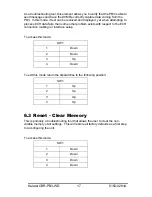
Страница 16: ...ected camera on a DVMRe Triplex This allows you to quickly check what settings are in your unit To access this mode SW1 1 Down 2 Down 3 Up 4 Up To exit this mode return the dipswitches to the following position SW1 1 Up 2 Up 3 Up 4 Up 6 2 Demo Simulated Message Mode This setting permits the PB3 to send a simulated ATM transaction message to the DVMRe Triplex This is useful for either for troublesh...

Страница 17: ... some other problem exists with respect to the ECR connection cabling or interface setup To access this mode SW1 1 Down 2 Down 3 Up 4 Down To exit this mode return the dipswitches to the following position SW1 1 Up 2 Up 3 Up 4 Up 6 3 Reset Clear Memory This is primarily a troubleshooting tool that allows the user to clear the non volatile memory of all settings This will restore all factory defaul...

Страница 18: ...3 WD 18 0150 0261A To exit this mode return the dipswitches to the following position SW1 1 Up 2 Up 3 Up 4 Up Power must be cycled OFF and then ON to the ProBridge unit before the reset command will take effect NOTE ...

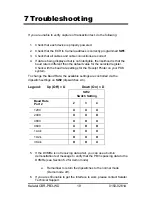
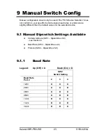
Страница 19: ...aud rate settings for the Receipt Printer on your POS system To change the Baud Rate the available settings are controlled via the dipswitch settings on SW2 dipswitches 2 4 Legend Up Off U Down On D SW2 Switch Setting Baud Rate Port 2 2 3 4 1200 U U U 2400 U U D 4800 U D U 9600 U D D 14 4k D U U 19 2k D U D 38 4k D D U 5 If the DVMRe is not receiving data at all you can use a built in demonstratio...

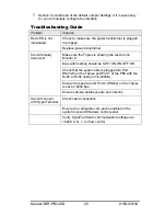
Страница 20: ...x on Monitor A Dip switch setting should be SW1 ON ON OFF ON Check that the serial cable is plugged into Port RS232 2 on the Triplex and Port 1 of the PB3 with the RJ45 to RJ45 cable 4310 0034B Ensure the baud rate for Port 2 RS232 on the Triplex is set to 19200 bps Cannot display demo text Ensure camera addresses are set correctly Cannot connect with HyperTerminal Check cable connection Ensure th...

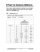
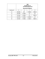
Страница 21: ...tches 5 8 Dipswitches 5 thru 8 on SW1 assigns transaction text for that cash register s PB3 unit to a specific camera on the DVMRe Legend Off Up On Down SW1 Dipswitch 5 8 Camera Assignment Dipswitch Numbers Camera 5 6 7 8 1 UP UP UP UP 2 UP UP UP DOWN 3 UP UP DOWN UP 4 UP UP DOWN DOWN 5 UP DOWN UP UP 6 UP DOWN UP DOWN 7 UP DOWN DOWN UP 8 UP DOWN DOWN DOWN 9 DOWN UP UP UP 10 DOWN UP UP DOWN 11 DOWN...

Страница 22: ...latel CBR PB3 WD 22 0150 0261A SW1 Dipswitch 5 8 Camera Assignment Dipswitch Numbers Camera 5 6 7 8 12 DOWN UP DOWN DOWN 13 DOWN DOWN UP UP 14 DOWN DOWN UP DOWN 15 DOWN DOWN DOWN UP 16 DOWN DOWN DOWN DOWN ...

Страница 23: ...ocols are slightly different than the default values for the selected device 9 1 Manual Dipswitch Settings Available q Camera Address SW1 Dipswitches 5 8 see Section 8 q Baud Rate SW2 Dipswitches 2 4 q Protocol SW2 Dipswitches 5 8 9 1 1 Baud Rate Legend Up Off U Down On D SW2 Switch Setting Baud Rate Port 2 2 3 4 1200 U U U 2400 U U D 4800 U D U 9600 U D D 14 4k D U U 19 2k D U D 38 4k D D U ...

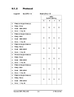
Страница 24: ...ynchronous q Parity Odd q Code 8 Bit ASCII q Mode 1 Stop Bit U D U U q Protocol Asynchronous q Parity None q Code 8 Bit ASCII q Mode 1 Stop Bit U U D D q Protocol Asynchronous q Parity Even q Code 7 Bit ASCII q Mode 1 Stop Bit U U D U q Protocol Asynchronous q Parity Odd q Code 7 Bit ASCII q Mode 1 Stop Bit U U U D q Protocol Asynchronous q Parity None q Code 7 Bit ASCII q Mode 1 Stop Bit U U U U ...

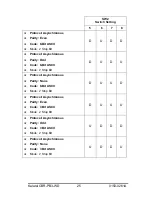
Страница 25: ...dd q Code 8 Bit ASCII q Mode 2 Stop Bit D U D U q Protocol Asynchronous q Parity None q Code 8 Bit ASCII q Mode 2 Stop Bit D U U D q Protocol Asynchronous q Parity Even q Code 7 Bit ASCII q Mode 2 Stop Bit D U U U q Protocol Asynchronous q Parity Odd q Code 7 Bit ASCII q Mode 2 Stop Bit U D D D q Protocol Asynchronous q Parity None q Code 7 Bit ASCII q Mode 2 Stop Bit U D D U ...

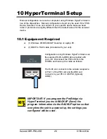
Страница 26: ... 98 NT 2000 XP Desktop or Laptop PC q 1 DB9F to RJ45 cable included with your unit Configuration using Windows HyperTerminal uses the supplied RJ45 to DB9 cable provided with your unit Disconnect the PB3 unit from the DVMRe and hook up the cable as follows The RJ45 end connects to the outside receptacle of Port 1 of the PB3 unit and the DB9 end connects to your PC s COM Port typically COM1 IMPORTA...

Страница 27: ...ILE NEW Give the connection a name and select an Icon Click OK 2 Under Connect Using option select COM1 3 The Com1 Properties menu will appear Select the following settings to complete the setup a Bits per Second 19200 b Data Bits 8 c Parity None d Stop Bits 1 e Flow Control None 4 Power up the ProBridge unit by plugging in the power supply ...

Страница 28: ... screen or similar will confirm that you are in HyperTerminal programming mode 2 Once HyperTerminal mode is set up press the Enter key twice The following menu will appear To make a menu selection enter the number of the element and press Enter For example Input the following 2 ENTER Port 2 Initializing from DIP Switches Kalatel ProBridge III POS Ver 2 10 Camera 16 Main Menu 1 Exit 2 Port 2 3 Back...

Страница 29: ...ns available for each element Entering the number for the element will switch to the next option for that element Continue to enter the same element number until the desired entry appears The menu options are presented similar to the following screen a Menu Selection 2 Protocol Options q Asynchronous RS 232 Options 1 Main Menu 2 Protocol Async 3 Baud Rate 9600 4 Parity None 5 Mode 1 stop 6 Code 8 ...

Страница 30: ...top bit q 2 Stop bit e Menu Selection 6 Code Character The available selections are q 7 Bit ASCII q 8 Bit ASCII f Menus Selection 7 Device Type q Generic Receipt Printer q Epson Printer q Citizen Printer q other printers may be included IMPORTANT You must BACKUP Save the program information via the BACKUP option so that everytime the unit is powered up the settings you configured will be used Go b...

Страница 31: ...of the DVMRe CD CS using the supplied RJ45 to DB9F cable ii The DVMRe communications port needs to be programmed as follows Communications RS 232 Port 1 ATM Activate b MODEM Connected to RS 232 1 Port of DVMRe CD CS i ProBridge Port 1 RJ45 connects to RS 232 2 Port of the DVMRe CD CS using a RJ45 to DB9M cable The provided RJ45 to DB9F cable can be used provided a Kalatel recommends using a DVMRe ...

Страница 32: ...insertion Transaction text is captured with video regardless of recording mode Time Lapse Time Lapse Event or Event only If Time Lapse Event or Event only recording modes must have at least one second set for the pre event duration Final Testing After hooking up the Duplex or Simplex unit have some POS transactions generated Allow sufficient time 2 3 minutes before stopping recording and performin...

Страница 33: ...n 8 Pin 7 Common Pin 6 A Pin 5 Rcv Pin 4 Tx Pin 3 A Pin 2 Pin 1 Common RJ 45 Connector RJ 45 Connector ProBridge to DVMRe DVMRe CD S Part Number 4310 0047B Communication Type RS232 Connector Type RJ 45 DB9F Cable Required 6 Foot RJ 45 to DB9F RS232 Cable Supplied Connects ProBridge to DVMRe CD CS NOTE This cable also used for Programming ProBridge via Windows HyperTerminal Pin 8 Pin 7 Pin 6 Pin 5 ...

Страница 34: ...ommon Pin 8 Pin 7 Common Pin 6 A Pin 5 Rcv Pin 4 Tx Pin 3 A Pin 2 Pin 1 Common RJ45 Connector RJ45 Connector ProBridge to ECR and Receipt Printer Part Number 4310 0078A Communication Type RS232 Connector Type DB9F to DB9M to DB9F Cable Required 6 Foot RS232 Cable Supplied Connects PB3 to the ECR and the Receipt Printer DB9F DB9M DB9F Connector Pin 8 Pin 8 Pin 8 Pin 7 Pin 7 Pin 7 Pin 6 Pin 6 Pin 6 ...

Страница 35: ...al Color Black Environmental Temperature 0 to 40 C operating Relative Humidity 90 non condensing Electrical AC Power External AC power supply included Voltage Range 110 to 240 VAC 10 Current 200 mA DC Power DC jack positive center Power Supply Voltage 12 VDC Current 110 mA Power 1 5 W All specifications are subject to change without notice Kalatel believes that all specifications are correct howev...

Страница 36: ...erica Telephone 800 343 3358 7 00 AM to 4 30 PM Pacific Time In Oregon 541 754 9133 Fax 541 754 7162 24 hours a day For warranty information see the following page 14 2 Warranty Kalatel warrants all of its equipment for three years from the date of purchase This warranty covers any defects in materials and workmanship Equipment failures that are due to improper installation modification abuse or a...

Страница 37: ...is required we will send the customer replacement equipment from our stock and receive the returned product in exchange The received equipment will be evaluated and the repair department will determine whether it is a warranty replacement If it is non warranty see our repair policy above for details The following guidelines will be used for all advance replacements Fewer than 45 days from purchase...

Отзывы: