


2
SM336MAN
Specifications: V.34, V.32 bis, V.32, V.22
bis, V.22A/B, V.23, V.21,
Bell 212, Bell 103, V.33,
V.17, V.29, V.27 ter, V.21
Channel
2
Error Correction….V.42 LAPM, MNP2-4,
MNP
10
Data Compression…V.42 bis, MNP 5
Loop Tests….. ITU V.54 loop2 (RDL) and
Loop 3 (LAL)
Transmit and Receive Frequencies:
Data Carrier…….1800
±
0.5 Hz
Calling Tone……1300
±
10 Hz
Answering Tone…2100
±
15 Hz
Receiver Freq. Tol…….
±
14 Hz
Receiver Performance
S/N Ratio…………..-26 dB
Dynamic Range……-12 dBm to –42 dBm
Transmit Level
Fixed at –11
±
2 dB
Ring detect Sensitivity…. 38 VRMS
LINE INTERFACE
Ring Equiv. Number….…1 Bel
Terminating Imped………600 Ohm
Return Loss… Better than 14 dB between
200 and 4000 Hz
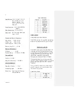
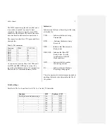
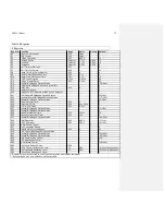
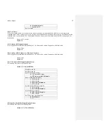
Table 1, DB-9 Pinout
Pin No.
EIA-232
1
DCD (out)
2 RXD
(out)
3 TXD
(in)
4 DTR
(in)
5 GND
6 DSR
(out)
7 RTS
(in)
8 CTS
(out)
9 RI
(out)
INDICATORS
TXD, RXD, DCD, DTR, DSR, RI.
The SM336 can store 2 user profiles and 4 phone
numbers. The numbers can have up to 32 digits.
INSTALLATION
The SM336 receives power from the Model 170
Controller, and the Controller should always be
powered down, or OFF for a minute or so before
inserting the SM336 into the card frame. This
should allow ample time for potentially
damaging power supply voltages to dissipate.
The incoming phone line is to be connected to
the RJ-11 connector labeled “LINE”. An external
phone can be connected to the RJ-11 labeled
“PHONE”.
Note: As the RJ11 connectors are connected in
parallel, remember not to use the phone while
the modem is in operation.
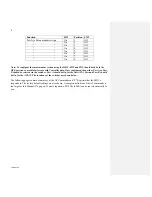
Table 2, RJ-11 Pinout
1 No
connection
2 TIP
3 RING
4 No
connection