


26
Front
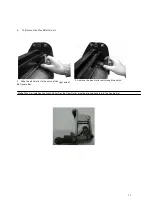
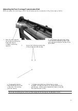
Cam roller pointing
downward squarely when
installing
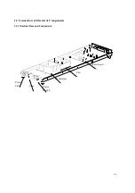
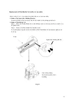
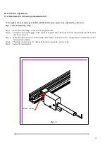
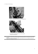
Replacement of Pinch Roller Set and Lever Assembly
Refer to Fig 1-2 to 1-3 to remove the pinch roller set or lever assembly.
1. Remove the Square Bar Holding Bracket.
Loosen and remove the two screws that fix the bracket to the carriage guide beam.
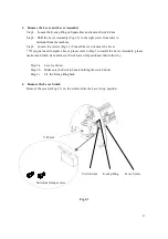
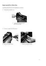
2. Remove Pinch Roller Set
Step 1. Move the Pincher Roller Set to the furtherest end (view from rear) where a notch is on
the guide beam.
Step 2. Remove the Pinch Roller Set from the notch.
To install, please keep the inside Cam Roller of the Pinch Roller Set downward squarely and
Lever up.
Front
Square Bar Holding Bracket
Cam roller pointing
downward squarely when
installing
Fig 1-2
Содержание Puma Series
Страница 4: ...4 Main Unit Assembly 29006178G...
Страница 7: ...7 Left End Assembly 7 1...
Страница 9: ...9 Right End Assembly 7 8...
Страница 13: ...13 Complete X motor Assembly 29003820G...
Страница 15: ...15 Y Axis Idel Pulley Assembly 29003820G...
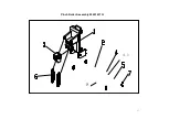
Страница 17: ...17 Pinch Roller Assembly 29001437G 4 1 8...
Страница 19: ...19 Grid Drum Assembly 29005441G...
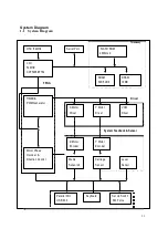
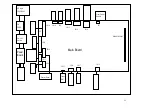
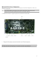
Страница 22: ...22 1 System Diagram and Components of Main Board...
Страница 57: ...57 Appendix Parts and Accessory List Spare Parts Customer Service Request Form To the Contents Page...


