Vhandy Technology
GC-3822 user manual
Serial number
Meaning
1
The first R (red signal line) input
2
The second R (red signal line) input
3
The first B (blue signal line) input
4
The second B (blue signal line) input
5
The first Y (yellow signal line) input
6
The second Y (yellow signal line) input
7
No input
8
No input
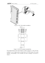
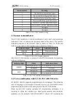
Table 2.1 GC-3822 module wiring
2.3 System statusindicator
The GC-3822 module has 2 red error indicators 2 and 4 and 2 green operation
indicators 1 and 3 to indicate the operating status of the device. The specific
indication function of the indicator light is shown in Table 2.2. When the
indicator is on, the GC-3822 module status is shown in Table2.3.
Indicator light
colour
Indication status
ERROR
red
Error indication
RUN
green
Operating instructions
Table 2.2 GC-3822 module indicator
After the GC-3822 module is connected to the PT100 normally, the operation
indicator will light up.
Indicator light
Status
Indication status
ERROR
Red light always on No temperature sensor access
not bright
No error
RUN
Always on
Connect correctly
not bright
No temperature sensor access
Table 2.3 GC-3822 module indicator status
2.4 Use in combination with GCAN-PLC-400/510 series
GCAN-PLC-400/510 supports programming in five languages. The following
uses ST language as an example to introduce how to use GCAN-PLC-400 to
program to read the status of the analog input of the GC-3822 module.
When the GC-3822 module performs ST programming definition, it is
necessary to define the variable type, input signal position, start character,
separator, etc. For example: "AI0 AT%I0.0:INT;", where "0.0" represents the

