background image

Page 4 of 28 

M434/500 Prototype Commissioning Manual 

PN W453101Rev- Nov-02-1998 


Boom Hoist Geometry 


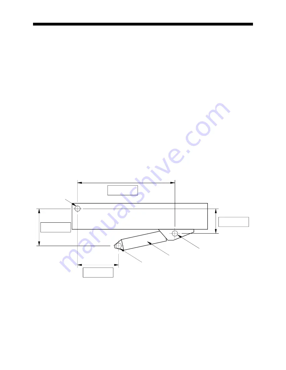
Measure each dimension shown using a tape.  It is at best, a difficult exercise to measure these 
dimensions, but still a necessary check.  It is recommended that two people carry out this task and that 
care is taken to ensure that clear references are used to measure from. 
 

Dimension “L”

 is the distance parallel to the boom center line between the center of the Boom pivot and 

the center of the upper Boom Hoist cylinder pivot. 
 

Dimension “J”

 is the distance at 90 degrees to the boom center line between the center of the Boom 

pivot and the center of the upper Boom Hoist cylinder pivot. 

J is negative when the Boom pivot is above the upper Boom Hoist cylinder pivot and positive when it is 
below


Dimension “G”

 is the horizontal distance between the center of the Boom Pivot and the center of the 

lower Boom Hoist cylinder pivot. 
 

Dimension “H”

 is the vertical distance between the center of the Boom pivot and the center of the lower 

Boom Hoist pivot. 
 
It is recommended that the boom is level when measuring dimensions “L” and “J”. 
The carrier is assumed to be level for the purposes of measuring dimensions “G” and “H”. 
  
Enter the measured values into each of the gray boxes provided below. 


*

  If the boom foot pin is above the Boom Hoist cylinder Upper Pivot (as shown), dimension “J” is 

negative.  

Clearly indicate “+” or “-“.

  The above illustration shows dimension “J” as negative. 


H

J

G

Boom Hoist Cylinder

Boom

Boom Pivot

Low er Pivot

Upper Pivot

L

*

Содержание MG 500

Страница 1: ...MG434 500 Prototype Commissioning Manual PN W453101Rev Nov 02 1998 MG 500 Rated Capacity Indicator System Prototype Calibration and Testing for Machine Model Serial Number Tester Date...

Страница 2: ...have already been entered as part of the capacity chip data entry 5 Charts It is highly recommended that each of these checks are methodically applied in order to save time and problems with future i...

Страница 3: ...mensions measured and verify that they match data within the capacity chip file If any discrepancies are found they must be immediately repaired and a new capacity chip created in order to continue Es...

Страница 4: ...oom Hoist cylinder pivot J is negative when the Boom pivot is above the upper Boom Hoist cylinder pivot and positive when it is below Dimension G is the horizontal distance between the center of the B...

Страница 5: ...n J0 is the distance at 90 degrees to the boom center line between the center of the Boom pivot and the point at which the hoist rope makes contact with the top sheave at the head of the main boom Dim...

Страница 6: ...n J1 is the distance at 90 degrees to the boom center line between the center of the Boom pivot and the point at which the hoist rope makes contact with the top sheave at the head of the main boom Dim...

Страница 7: ...tion checks Before continuing make sure any necessary changes to geometrical data found in the previous pages have been made to the capacity chip file and a new capacity chip has been created and inst...

Страница 8: ...at the boom is fully retracted prior to setting Set the reeling Drum zero by measuring the drive voltage and adjusting the pot until the extension voltage is equal to 1 20 th of the drive voltage 0 25...

Страница 9: ...and deflection for each telescoping mode of the main boom Almost all machines have two telescoping modes of operation for the boom This would include Main boom manual retracted Main boom manual extend...

Страница 10: ...ully retracted and fully extended calibration Some booms exhibit a sudden droop near to fully telescoped this is often due to the design and fitting of wear pads inside the boom which allow sections t...

Страница 11: ...____ Boom Extension 0 Boom Extension 1 Boom Extension 2 Boom Extension 3 Boom Extension 4 Boom Extension 5 Boom Extnsion 6 EXTN LEN_S WG WT Boom ________ Boom Extension 0 Boom Extension 1 Boom Extensi...

Страница 12: ...ollowing the instructions in the calibration manual It is a good idea to add 0 1ft or 0 1m to the radius when entering the radius in the calibration for boom deflection This will help ensure a slightl...

Страница 13: ...he boom and attach an inclinometer to the boom head Set the boom level 0 0 degrees and set the inclinometer to read 0 0 degrees use zero reference button if the inclinometer has one Telescope the boom...

Страница 14: ...28 M434 500 Prototype Commissioning Manual PN W453101Rev Nov 02 1998 Boom ________ Boom Extension Boom Angle Boom Head Angle Difference Boom ________ Boom Extension Boom Angle Boom Head Angle Differe...

Страница 15: ...hat will sufficiently show the accuracy of the calibration in all working areas of the main boom Test the unladen boom two different loads at three different lengths and three different angles for eac...

Страница 16: ...of 28 M434 500 Prototype Commissioning Manual PN W453101Rev Nov 02 1998 Boom ________ Displayed Length Displayed Angle Displayed Radius Measur d Radius Radius Error Displayed Load Actual Load Load Err...

Страница 17: ...of 28 M434 500 Prototype Commissioning Manual PN W453101Rev Nov 02 1998 Boom ________ Displayed Length Displayed Angle Displayed Radius Measur d Radius Radius Error Displayed Load Actual Load Load Err...

Страница 18: ...s only a short extension to the main boom Check that the auxiliary head dimensions specified in the capacity chip file either specify an effective vertical and horizontal offset or length and angular...

Страница 19: ...the straightest offset angle It is a good idea to check the length and vertical offset dimensions of the attachment with a tape before commencing tests If necessary correct the values of these in the...

Страница 20: ...totype Commissioning Manual PN W453101Rev Nov 02 1998 Attachment Tests Attachment Offset Main Boom Test Test Displayed Length Displayed Angle Displayed Radius Measur d Radius Radius Error Displayed Lo...

Страница 21: ...totype Commissioning Manual PN W453101Rev Nov 02 1998 Attachment Tests Attachment Offset Main Boom Test Test Displayed Length Displayed Angle Displayed Radius Measur d Radius Radius Error Displayed Lo...

Страница 22: ...totype Commissioning Manual PN W453101Rev Nov 02 1998 Attachment Tests Attachment Offset Main Boom Test Test Displayed Length Displayed Angle Displayed Radius Measur d Radius Radius Error Displayed Lo...

Страница 23: ...totype Commissioning Manual PN W453101Rev Nov 02 1998 Attachment Tests Attachment Offset Main Boom Test Test Displayed Length Displayed Angle Displayed Radius Measur d Radius Radius Error Displayed Lo...

Страница 24: ...totype Commissioning Manual PN W453101Rev Nov 02 1998 Attachment Tests Attachment Offset Main Boom Test Test Displayed Length Displayed Angle Displayed Radius Measur d Radius Radius Error Displayed Lo...

Страница 25: ...totype Commissioning Manual PN W453101Rev Nov 02 1998 Attachment Tests Attachment Offset Main Boom Test Test Displayed Length Displayed Angle Displayed Radius Measur d Radius Radius Error Displayed Lo...

Страница 26: ...totype Commissioning Manual PN W453101Rev Nov 02 1998 Attachment Tests Attachment Offset Main Boom Test Test Displayed Length Displayed Angle Displayed Radius Measur d Radius Radius Error Displayed Lo...

Страница 27: ...totype Commissioning Manual PN W453101Rev Nov 02 1998 Attachment Tests Attachment Offset Main Boom Test Test Displayed Length Displayed Angle Displayed Radius Measur d Radius Radius Error Displayed Lo...

Страница 28: ...oughly check that all data from the calibration that needs to entered into the capacity chip has been and that the latest copy of the chip is installed in the system computer This will ensure that in...

Отзывы: