background image

GBC Films Group

4151 Anderson Road

DeForest, WI   53532

Revision :                                                                                                                                        Ph: ( 608 ) 246 - 8844

Fx: ( 608 ) 246 - 8645

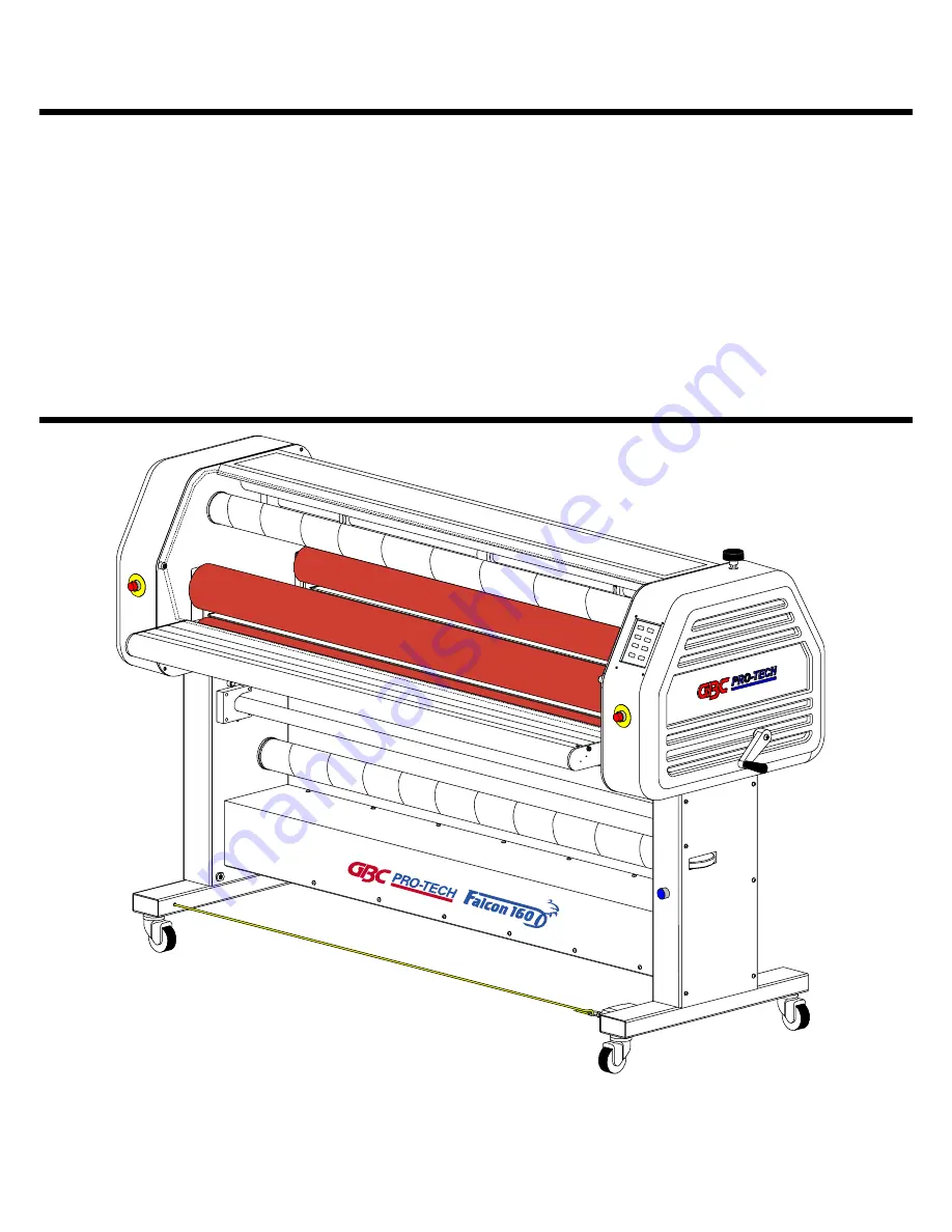
F - 160 CE OPERATION AND

MAINTENANCE MANUAL

© April 2000 GBC Films Group

Do not duplicate without written permission.

Part number : 930 - 065

Содержание F - 160 CE

Страница 1: ...p 4151 Anderson Road DeForest WI 53532 Revision Ph 608 246 8844 Fx 608 246 8645 F 160 CE OPERATION AND MAINTENANCE MANUAL April 2000 GBC Films Group Do not duplicate without written permission Part nu...

Страница 2: ...y 1 1 Symbols 1 1 1 2 Safety features 1 2 1 3 Safety shield 1 3 1 4 Emergency stop 1 4 1 5 Emergency cable 1 5 1 6 Front feed table 1 6 1 7 Decal locations 1 7 Figure 1 7 1 Decal location front 1 9 Fi...

Страница 3: ...eneral 3 1 3 2 Consumables 3 1 3 3 Function 3 2 3 4 Electrical 3 3 3 5 Dimensions 3 4 Figure 3 5 1 Dimensions 3 5 Section 4 Installation 4 1 Preinstallation check list 4 1 Figure 4 1 1 Suggested floor...

Страница 4: ...5 Figure 4 9 1 Single phase U S Canada 4 17 Figure 4 9 2 Three phase Europe 4 17 4 10 Safety check 4 18 4 10 1 Front feed table 4 18 4 10 2 Safety shield 4 20 4 10 3 E STOP 4 21 4 10 4 E CABLE 4 22 4...

Страница 5: ...1 1 Front control panel 5 9 5 2 Emergency 5 10 5 2 1 In an emergency 5 10 5 2 2 Resume operation 5 11 5 3 Set up 5 12 5 3 1 Power 5 12 5 3 2 Film loading 5 12 Chart 5 3 1 Measurement chart 5 14 5 3 5...

Страница 6: ...e 5 24 5 6 1 Removing the table 5 24 5 6 2 Replacing the table 5 24 Section 6 Applications 6 1 Parameter charts and diagrams Chart 6 1 1 Temperature conversion chart 6 3 Blank chart 6 4 Blank diagram...

Страница 7: ...t Decal 6 14 Diagram 5 Decal and mount Decal 6 15 Chart 6 Decal and mount Mount 6 16 Diagram 6 Decal and mount Mount 6 17 Chart 7 Precoating subtrates 6 18 Diagram 7 Precoating subtrates 6 19 Chart 8...

Страница 8: ...Encapsulation 6 27 Section 7 Troubleshooting 7 1 Wave problems 7 1 7 2 Film problems 7 3 7 2 1 Thermal laminates 7 3 7 2 2 Pressure senstive 7 3 7 3 Machine problems 7 4 7 4 Glossary 7 5 Section 8 Ma...

Страница 9: ...Page VIII Table of Contents F 160 CE Operation and Maintenance Manual GBC Films Group April 2000 This page intentionally left blank...

Страница 10: ...RMATION Indicates helpful information that should be considered before during or after an action step or procedure is given CAUTION Indicates a potentially hazardous situation which if not avoided cou...

Страница 11: ...ickly in an emergency The main laminator roll up down control is located on the right side of the machine within the front control panel The GAP up down arrows control the motion of the upperlaminatin...

Страница 12: ...components for the safety of the operator Figure 1 2 1illustrates placement of the cabinets and covers Figure 1 2 1 Cabinets and covers Covers Cabinets 1 3 Safety shield An important feature of the F...

Страница 13: ...Front Rear Emergency stops Emergency stops ToengageanE STOP pressdownonanyofthe four Any E STOP when engaged removes power to thelaminator RefertoFigure1 4 2EngageanE STOP Figure 1 4 2 Engage an E STO...

Страница 14: ...ot to activate an emergency cable E CABLE located at the base of the stand from the front or rear of the machine Refer to Figure 1 5 1 Emergency cable INFORMATION The machine will only operate if the...

Страница 15: ...Front feed table The front feed table must be in proper position for the laminator to operate in auto run Refer to Figure 1 6 1 Front feed table Whenthekeyisremovedfromtheinterlock the laminatorwillst...

Страница 16: ...de secousse electrique Ne pas ouvrir Pas de pieces reparables par l utilisateur Entretien par personnel qualifie WARNING Electrical shock hazard Do not open No user serviceable parts inside Refer serv...

Страница 17: ...1 8 Safety F 160CE Operation and Maintenance Manual GBC Films Group April 2000 Reset Machine reset Press after iniating power to the laminator or after an E STOP or E CABLE has been engaged then rese...

Страница 18: ...lifie WARNING Electrical shock hazard Do not open No user serviceable parts inside Refer servicing to qualified service personnel WARNING ACHTUNG MISE EN GARDE WARNING ACHTUNG MISE EN GARDE WAARSCHUWI...

Страница 19: ...sfUhrend e Teile Nicht offnen Enthalt keine vom Enduerbraucher zu wartende Teile Fur service bitte an qualifiziertes Service Personal wenden MUCHO CUIDADO Riesgo de choque electrico No abra Adentro no...

Страница 20: ...erdamage to the laminating rollers caused by knives razor blades other sharp objects failure caused by adhesives or improper use of the machine Warranty repair or replacement does not extend the warra...

Страница 21: ...engineers should be fully aware of all aspects of safety withregardstolaminationequipment Anycommissioningorserviceengineermustbe ofcompetentnature trainedandqualifiedtoGBCFilms Group standards to ful...

Страница 22: ...l wide format color finisher for the sheet fed ink jet market The Falcon 160 CE is a self standing bi directionallaminator Two unwinds 1 upper 1 lower Two rewinds 1 upper front 1 lower center Safetysh...

Страница 23: ...Up to a 8 roll diameter 20 3 cm 3 core standard 7 62 cm 2 1 4 optional must have optional core adapters 5 72 cm 64 Pressure sensitive 162 6 cm 62 Thermal 157 8 cm 62 maximum paper width 157 8 cm Up to...

Страница 24: ...eater wattages Amperagedraw D C voltage used A C voltage used Save up to 9 job parameters Highreleasesiliconerolls 230 240 VAC 50 60 Hz single phase 55 amps 230 240 VAC Wye 3 phase 32 amps phase 31 73...

Страница 25: ...imensions Weight Crated Uncrated Dimensions Crated Uncrated Nip Height Safety Shield Raised Height 1568 lbs 711 kg 1200 lbs 544 kg 90 in H x 46 in W x 72 in L 229 cm H x 117 cm W x 183 cm L 54 in H x...

Страница 26: ...ifications F 160 CE Operation and Maintenance Manual GBC Films Group April 2000 Figure 3 5 1 Dimensions 76 in 193 cm 28 in 71 cm 4 875 in 12 cm 4 75 in 12 cm 53 in 135 cm 82 5 in 210 cm 3 63 in 9 cm 1...

Страница 27: ...Page 3 6 Specifications F 160CE Operation and Maintenance Manual GBC Films Group April 2000 This page intentionally left blank...

Страница 28: ...laminator A work area must be established that allows for operation in both the front and rear of the laminatorandprovidesspaceforefficientmaterial flow Figure 4 1 1 illustrates a typical machine area...

Страница 29: ...nator is a large and heavy piece of equipment It is necessary to employ LICENSED RIGGERS ONLY to move the laminator The laminator is not designed to be tipped up or sideways in any way Such action dis...

Страница 30: ...ual GBC Films Group April 2000 Figure 4 1 1 Suggested Floor Layout 4 x 6 1 22 m x 2m Work table on wheels Table height 35 3 4 94 95m 4 x 6 1 22 m x 2m Work table on wheels Table height 35 3 4 94 95m 3...

Страница 31: ...ide leg Drive side leg Front side Figure 4 2 2 Safety features Rear safety shield E CABLE E STOP E STOP Front safety shield E CABLE reset Machine reset Figure 4 2 3 Front view Lower unwind shaft Lower...

Страница 32: ...Please follow the unpacking procedure that pertains to your method of shipment WARNING The unpacking process requires at least two people You can be severely injured crushed or cause damage to the lam...

Страница 33: ...shandling and or tipping GBC Films Group bears no responsibility for personal injury or damage due to moving the laminator improperly INFORMATION Tools required 2 Phillips head screwdriver 7 8 open en...

Страница 34: ...laminator You can cause irreparable damage to the rollers b Move all packing materials to a safe distance Moving the laminator a Have the laminator rolled off the skid and placedonthefloorbylicensedri...

Страница 35: ...s 645 011 Twelve 3 4 10 nuts No P N If you are missing any of the itemslisted above contact your local service technician or sales representative Contacts GBC Parts 800 790 7787 GBC Europe parts 33 45...

Страница 36: ...wrenches Fourlevelingpads from the accessory pack FourLevelingbolts from the accessory pack Twelve 3 4 10 nuts from the accessory pack Floor jack 600 pound rating Second person Control side a Verifyt...

Страница 37: ...ng pad Drive side a Perform steps a through j from the Control side e Remove the front control side castor by turning thenutsecuring the castor in the leg Castor Nut f Slide one of the leveling bolts...

Страница 38: ...ront to back control side 4 8 1 Front to back control side Level The side frame provides a more accurate reading than the cabinet INFORMATION b Level the control side from front to back by holdingthen...

Страница 39: ...side Figure 4 8 2 Front to back drive side Level d Level the control side from front to back by holdingthenutinsidethelegandturningthenut belowthelegwiththewrench INFORMATION A second person can read...

Страница 40: ...PS are unlatched and the E CABLE is reset before turning power on to the laminator INFORMATION h Press RESET The front control panel should beilluminatedatthispoint Machine reset Caution should always...

Страница 41: ...lace the level across the top of the upper main roller in the center Refer to Figure 4 8 3 Drive to control side front Figure 4 8 3 Drive to control side front Level l Levelthelaminatorfromdrivesideto...

Страница 42: ...to control side rear Figure 4 8 4 Drive to control side rear Level p Verify allfourlevelingpoints Makeany adjustmentsneccessary Ifallfourpointsare leveled secureallnutsinplace q Lower the front and r...

Страница 43: ...ator d Connect the power cord to the line terminal block Refer to Figure 4 9 1 Single phase or Figure 4 9 2 Wye three phase Figure 4 9 1 Single phase illustrates proper single phase wiring for the U S...

Страница 44: ...intenance Manual GBC Films Group April 2000 Figure 4 9 1 Single phase U S and Canada Figure 4 9 2 Wye 3 phase Europe only N L1 L2 L3 N N N PE Ground wire Line 2 Line 1 N L1 L2 L3 N N N PE Ground wire...

Страница 45: ...removable ALL SAFETY FEATURES MUST BE CHECKED WARNING Do not wear ties loose fit clothing or dangling jewelry while operating or servicing the laminator These items can get caught in the nip and chok...

Страница 46: ...Y FWD REV 6 0 GO STOP f Press GO The bottom rollers begin turning SPEED SAFETY FWD REV 6 0 GO STOP g Slightlyliftthefrontfeedtable SAFETY indicatorandGObeginflashingandthe bottom rollers stop SPEED SA...

Страница 47: ...with the safety shields raised You can be seriously HURT or INJURED WARNING b Raisethefrontsafetyshield SAFETYindicator andGObeginflashingandthebottomrollers stop SPEED SAFETY FWD REV 6 0 G STOP Flash...

Страница 48: ...inate 3 bars in thepressuredsiplay 0 GAP PRESSURE c Press down on the front control side E STOP The E STOP latches in the down position bottom rollers stop the upper main roller raises and the control...

Страница 49: ...3 bars in thepressuredsiplay 0 GAP PRESSURE c Press on the front E CABLE with your foot The bottom rollers stop the upper main roller raises and the control panel is blank d Latch the E CABLEby pushin...

Страница 50: ...aminator These items can get caught in the nip and choke you or you can be crushed or burned 4 11 1 Control panel a Press TOP TEMP to a value of 120o F 48 o C TOP TEMP DISPLAY begins flashing 120 68 T...

Страница 51: ...ler thebarsturnsolidoneatatimeuntil all 10 bars are solid 0 GAP PRESSURE g Press and hold PRESSURE The upper main roller travels in a constant upward motion The pressure bars turn hollow one at a time...

Страница 52: ...D SAFETY FWD REV 15 0 GO STOP l Press GO The bottom rollers turn in a forward motion at a speed of 15 ft min 4 57 m min SPEED SAFETY FWD REV 15 0 GO STOP m PressSTOP Thebottomrollersstopturning SPEED...

Страница 53: ...emperature is within a 6 o F of the set point temperature 120 120 TOP TEMP BOT TEMP Caution should always be exercised when using the laminator with the safety shields raised You can be seriously HURT...

Страница 54: ...SSURE IIIIIII 0 JOB STANDBY SAV SPEED SAFETY GO STOP FWD REV 00 0 SE L Flashing 4 11 2 Variable speed footswitch Thischeckistoensurethatthefootswitchworks Forcompleteinstructionsonthefootswitchanditsr...

Страница 55: ...Should you detect or experience complications with the unwind shaft movement or the unwind brake tension callyoulocalareaservicerepresentative Caution should always be exercised when using the laminat...

Страница 56: ...er unwind brake adjustment dial g You should feel an increase in resistance on the turningoftheupperunwindshaftasyouturnthe upper unwind brake adjustment knob clockwise h Slowlyturntheupperunwindbrake...

Страница 57: ...Page 4 30 Installation F 160 CE Operation and Maintenance Manual GBC Films Group April 2000 This page intentionally left blank...

Страница 58: ...oursofnoactivity Towake thelaminatorfromstandbymodeormanualengagestandby mode press STANDBY JOB STANDBY SEL SAV 0 1 2 TOPTEMPDISPLAY Thedisplaywillshowthe setpointtemperatureofthetopmainrollerasthedef...

Страница 59: ...TOP TEMP BOT TEMP 6 7 BOT TEMP When pressed will decrease the setpointvalueofthebottommainrollerinincrementsof 2 degrees If held down it will decrease to the minimum temperature setting of 68o F 20o...

Страница 60: ...inated equals100 ofthemaximumallowablepressure 1 16 GAP PRESSURE 12 INFORMATION When adjusting the pressure the gap will be affected as well 13 PRESSURE When pressed once will decreasethepressureby5 I...

Страница 61: ...d andheld theJOBDISPLAYwillincreaseto9atwhich pointitwillstop JOB STANDBY SEL SAV 9 16 17 JOB When pressed once will decrease the job numberinJOBDISPLAYbyincrementsof1 Ifpressed andheld theJOBDISPLAYw...

Страница 62: ...omaticallyincreaseby0 5ft min incrementsuntilithasreachedthemaximumallowedspeed of15ft min SPEED SAFETY FWD REV 15 0 STOP GO 21 22 SPEED When pressed decreases the speed ofthelaminatorinincrementsof0...

Страница 63: ...ETY FWD REV 00 0 STOP GO 27 28 Variable Speed Footswitch The variable speed footswitch operatesthelaminatorin Footswitch mode Within this mode if the safety shield is up speed is determined by the var...

Страница 64: ...he variable speed footswitch Release GO GO should be solid 3 In the event that the safety shield must be raised whilethelaminatorisrunning Performthefollowing steps INFORMATION If the variable speed f...

Страница 65: ...indicated panel speed INFORMATION When the safety shield is raised the laminator will only run while the variable speed footswitch is depressed Adjust for desired speed using the variable speed foots...

Страница 66: ...Manual GBC Films Group April 2000 Figure 5 1 1 Front control panel Flashing 1 68 68 TOP TEMP BOT TEMP 1 16 GAP PRESSURE IIIIIII 0 JOB STANDBY SAV SPEED SAFETY GO STOP FWD REV 00 0 SE L 2 3 4 5 6 7 8 9...

Страница 67: ...e upper main roller is capable of producing forces greater than 400 pounds WARNING This force is applied to any object presented in the opening called the nip between the two rollers Usecareinlowering...

Страница 68: ...ineRESET All parameters have defaulted Machine reset INFORMATION Once RESET has been engaged power will be restored Laminating rollers will reset to 1 in GAP and the display will return to it s defaul...

Страница 69: ...cedures descibed in Section 6 1 Application 5 3 1 Power a Clear the area around the laminating rollers and pullrollersnip b Ensurethelaminatorispluggedin c Turn the MAIN POWER to the I position Power...

Страница 70: ...e unwind shaft back into the saddle Ensure the roll of laminate is loaded properly on the unwind shaft Exposed adhesive should be facing away from the rollers This will prevent hours of roll cleaning...

Страница 71: ...the lower unwind shaft add 1 4 in to the measurement 5 3 5 Heating Perform the following steps if the application requiresheat Allowtherollstoheatupwhilerotatingfor evenheatdisbursement a Press TOP TE...

Страница 72: ...on SPEED SAFETY FWD REV 00 0 GO STOP e Press SPEED to set a speed of 2 ft min 61 m min SPEED SAFETY FWD REV 2 0 GO STOP A slow speed helps distribute heat evenly INFORMATION f Press SEL to engage the...

Страница 73: ...de TOP TEMP 68 o F 20 o C BOT TEMP 68 oF 20 oC GAP 1 in PRESSURE no bars are solid JOB 0 no motion direction selected SPEED 00 0 and SLEEP flashing b Press JOB to enter the desired job number for the...

Страница 74: ...old SAVE approximately 4 seconds until an audible beep is heard The parameters entered have just been stored JOB STANDBY SEL SAV 1 h Repeat steps b through f to save other parametersinjoblocationnumbe...

Страница 75: ...areperformingamountingapplicationfrom therearofthemachine thepullrollersmustbesetmanually Refer to Section 5 5 2 Pull roller nip adjustment procedure 5 5 1 Main roller manual nip adjustment The lamina...

Страница 76: ...d fingers clear of the laminator roller nip when changing GAP You can be CRUSHED or BURNED f At eye level with the main rollers press PRESSURE until you see the upper main roller make contact with the...

Страница 77: ...PEED to 5 SPEED SAFETY FWD REV 5 0 GO STOP WARNING When operating the laminator using the variable speed footswitch keep hands and fingers away from the nip of the rollers You may be CRUSHED or BURNED...

Страница 78: ...2 Pull roller manual nip adjustment If the main laminating rollers are heated mounting application may be run from the rear operating position of the machine INFORMATION a Turn the MAIN POWER to the I...

Страница 79: ...y shield h Position the leader board in the center of the pullrollersbetweenthenip CAUTION Sharp edges on a substrate should be filed smooth and GAP manually adjusted Sharp edges can CUT the rollers W...

Страница 80: ...board Excessive pressure Density of the substrate will determine the amount of pressure you may use INFORMATION WARNING When operating the laminator using the variable speed footswitch keep hands and...

Страница 81: ...ethefrontfeedtableproperly positionedbeforeusingthelaminatorforanapplication CAUTION If not installed properly you can be injured or cause damage to the table or laminator 5 6 1 Removing the table Cau...

Страница 82: ...both hands grip the front edge of the infeed table and align the back edge with the support bolts Front support bolt c Now lower the front edge while ensuring that thepinalignswiththesafetyrollerswitc...

Страница 83: ...Page 5 26 Operations F 160 CE Operation and Maintenance Manual GBC Films Group April 2000 This page intentionally left blank...

Страница 84: ...rolchart anddiagramfortheFalcon160CEaswellascompleted charts and diagrams for the basic operations of the laminator Itisrecommendedthatyoumakecopiesofthe blanksandfilltheminasneeded WARNING Do not wea...

Страница 85: ...charts and webupdiagramsinthemanualforreference Makecopies ifyourequiretheminotherlocations Use the blank parameter chart and blank web up diagram to record specific applications not illustrated in t...

Страница 86: ...4 78 9 175 79 4 176 80 177 80 6 178 81 1 179 81 7 180 82 2 181 82 8 182 83 3 183 83 9 184 84 4 185 85 186 85 6 187 86 1 188 86 7 189 87 2 190 87 8 191 88 3 192 88 9 193 89 4 194 90 195 90 6 196 91 1 1...

Страница 87: ...Manual Parameter Chart Blank TEMPERATURE GAP PRESSURE MOTOR DIRECTION SPEED TOP TEMP BOT TEMP PRESSURE GAP SPEED FWR REV GO GO Panel SOLID FLASHING Footswitch PULL ROLL SETTINGS NOTES N A 1 4 Turn 1 2...

Страница 88: ...Page 6 5 Applications F 160 CE Operation and Maintenance Manual GBC Films Group April 2000 Web Diagram Blank...

Страница 89: ...4 Turn 1 2 Turn 3 4 Turn PRESSURE MATERIALS UPPER UNWIND LOWER UNWIND SUBSTRATE PRINTS Pro Mount N A 1 4 Foam Core N A 68 68 1 4 00 0 Pro Mount can be substituted with a similar product Substrate can...

Страница 90: ...Page 6 7 Applications F 160 CE Operation and Maintenance Manual GBC Films Group April 2000 Web Diagram 1 Precoating substrate Pro Mount Leader board Substrate...

Страница 91: ...N A 1 4 Turn 1 2 Turn 3 4 Turn PRESSURE MATERIALS UPPER UNWIND LOWER UNWIND SUBSTRATE PRINTS N A N A Precoated boards Inkjet prints 68 68 1 4 00 0 Substrate will vary Print can be of any type GAP wil...

Страница 92: ...Page 6 9 Applications F 160 CE Operation and Maintenance Manual GBC Films Group April 2000 Web Diagram 2 Mounting only Precoated board Release liner Print...

Страница 93: ...S N A 1 4 Turn 1 2 Turn 3 4 Turn PRESSURE MATERIALS UPPER UNWIND LOWER UNWIND SUBSTRATE PRINTS Pro Gloss N A 1 4 Foam Core Inkjet prints 68 68 1 4 00 0 Substrate will vary Print can be of any type GAP...

Страница 94: ...Page 6 11 Applications F 160 CE Operation and Maintenance Manual GBC Films Group April 2000 Web Diagram 3 Single sided Sled Sled Print P S A Laminate Release liner...

Страница 95: ...ES N A 1 4 Turn 1 2 Turn 3 4 Turn PRESSURE MATERIALS UPPER UNWIND LOWER UNWIND SUBSTRATE PRINTS Pro Gloss Craft Paper N A Inkjet prints 68 68 0 3 6 Upper unwind material can be of similar product Prin...

Страница 96: ...3 Applications F 160 CE Operation and Maintenance Manual GBC Films Group April 2000 Web Diagram 4 Single sided Craft paper Craft Paper Print P S A Lam inate Release liner Finish product rew ind option...

Страница 97: ...1 4 Turn 1 2 Turn 3 4 Turn PRESSURE MATERIALS UPPER UNWIND LOWER UNWIND SUBSTRATE PRINTS Pro Gloss Pro Mount N A Inkjet prints 68 68 0 3 6 Upper and lower unwind material can be of similar product Pr...

Страница 98: ...6 15 Applications F 160 CE Operation and Maintenance Manual GBC Films Group April 2000 Web Diagram 5 Decal and mount Decal Pro Mount Print P S A Laminate Release liner Finish product rewind option Ou...

Страница 99: ...urn 1 2 Turn 3 4 Turn PRESSURE MATERIALS UPPER UNWIND LOWER UNWIND SUBSTRATE PRINTS N A N A 1 4 Foam Core Decals 68 68 1 4 00 0 Decal will come from the previous chart and diagram application Substrat...

Страница 100: ...Page 6 17 Applications F 160 CE Operation and Maintenance Manual GBC Films Group April 2000 Web Diagram 6 Decal and mount Mount Substrate Release liner Decal...

Страница 101: ...E MATERIALS UPPER UNWIND LOWER UNWIND SUBSTRATE PRINTS Hot Tissue Mount N A 1 4 Foam Core N A 140 68 1 4 00 0 Upper unwind material may be sibstituted with similar product Substrate can vary Top tempe...

Страница 102: ...Page 6 19 Applications F 160 CE Operation and Maintenance Manual GBC Films Group April 2000 Web Diagram 7 Precoating substrate Thermal Hot Tissue Leader board Substrate 140 160...

Страница 103: ...WER UNWIND SUBSTRATE PRINTS 3 mil Octiva Gloss N A 1 4 Foam Core Electrostatic images 240 68 1 4 00 0 Upper unwind material may be sibstituted with similar product Substrate can vary Top temperature w...

Страница 104: ...Page 6 21 Applications F 160 CE Operation and Maintenance Manual GBC Films Group April 2000 Web Diagram 8 One pass mount and laminate Octiva Gloss Leader board Substrate 240 260 Hot Tissue Image...

Страница 105: ...A 1 4 Turn 1 2 Turn 3 4 Turn PRESSURE MATERIALS UPPER UNWIND LOWER UNWIND SUBSTRATE PRINTS 3 mil Octiva Gloss Pro Mount N A Any type 230 68 0 3 6 Upper and lower unwind material can be of similar pro...

Страница 106: ...ge 6 23 Applications F 160 CE Operation and Maintenance Manual GBC Films Group April 2000 Web Diagram 9 Thermal decal and mount Decal Pro Mount Print Octiva Gloss Finish product rewind option Output 2...

Страница 107: ...h PULL ROLL SETTINGS NOTES N A 1 4 Turn 1 2 Turn 3 4 Turn PRESSURE MATERIALS UPPER UNWIND LOWER UNWIND SUBSTRATE PRINTS N A N A Decals 68 68 1 0 00 The mounting process is done from the rear position...

Страница 108: ...Page 6 25 Applications F 160 CE Operation and Maintenance Manual GBC Films Group April 2000 Web Diagram 10 Thermal decal and mount Mount Substrate Release liner Decal...

Страница 109: ...ERIALS UPPER UNWIND LOWER UNWIND SUBSTRATE PRINTS 3 mil Octiva Gloss N A Any type 240 240 0 0 7 Upper and lower unwind material may be sibstituted with similar products Top and bottom temperature will...

Страница 110: ...Page 6 27 Applications F 160 CE Operation and Maintenance Manual GBC Films Group April 2000 Web Diagram 11 Encapsulation Octiva Gloss Print Octiva Gloss Finish product rewind option Output 230 230...

Страница 111: ...Page 6 28 Applications GBC Films Group April 2000 F 160 CE Operation and Maintenance Manual This page intentionally left blank...

Страница 112: ...empt to correct your typical output typeproblems Usetheeasytofollowguideforassistance 7 1 Wave problems Thefollowingisalistofcommonoutputwave problemsyoumayencounter Thearrowalongthelengthoftheoutput...

Страница 113: ...heck the nip setting of main rolls Checkthenipsettingofpullrolls Check for even paper tension Problem Angled waves in the output on both sides Hints Checkforinsufficientmainrollerpressure Checkforinsu...

Страница 114: ...the same Changethechillidlerconfiguration if applicable Problem Silveringinthelaminate Hints Decrease the speed Increase the operating temperature Problem Delamination Hints Check operating temperatur...

Страница 115: ...C Films Group suggest or recommend that you attempt to fix the machine by removingthecabinetsorlegcoversyourself WARNING Do not wear ties loose fitting clothing or dangling jewelry while operating or...

Страница 116: ...T Disconnect power and then reconnect power Placeaservicecallimmediatelyandremove all power to the laminator CAUTION Prolonged contact can form flat spots on the rollers 7 4 Glossary Theglossarycanhel...

Страница 117: ...adhesiveseparatingfromthelaminatesubstrate or2 the laminateseparatingfromtheproductbeinglaminated Edgewrap A mounting technique where the image wraps aroundtheedgesofthemountingsubstratesoastoprovide...

Страница 118: ...as This is seen as a cloudy or murkyfinishedimage Itcanalsobecausedbyachemical incompatibilitybetweentheoverlaminate sadhesiveand theprintedmedia Pull rollers These rolls provide for tension of the la...

Страница 119: ...small amount of heat is applied during the application Substrate Thematerialtowhichanadhesiveistobebonded Infilm thesubstrateisthepolyesterandinmounting the substrateisthematerialbeingmountedto Tunnel...

Страница 120: ...OCK Remove power from the laminator before servicing You can be severely shocked electrocuted or cause a fire 8 1 Maintenance Schedule Below is a recommended maintenance schedule Before performing any...

Страница 121: ...cked electrocuted or cause a fire 8 2 Cleaning the rollers Tools required Adhesive coated boards picks up dust and particles off of the rolls Protective rubber gloves Thiswillprotectyourhandsfromtheis...

Страница 122: ...ive adhesives put on the rubber gloves and use isopropyl alcohol and a terryclothtowel b Forthermaladhesives whilethelaminatorisat normal operating temperature put on the rubber gloves and use the rub...

Страница 123: ...may be CRUSHED or BURNED d Since the safety shields are raised and the tables removed you must use the footswitch to rotate the bottom rollers after cleaning a section Speed is controlled through the...

Страница 124: ...g the laminating rollers with 80 isopropyl alcohol Use only in a well ventilated area Wear rubber gloves Use only on cool rolls CLEANING HEATED ROLLERS CAN IGNITE THE FUMES WARNING When operating the...

Страница 125: ...tor roller nip when changing GAP You can be CRUSHED or BURNED d Position the center of the board between the rollers e Set the nip of the rollers to the thickness of the adhesive coated boards 1 4 GAP...

Страница 126: ...or Do not spill liquid of any kind on the laminator You can be severely shocked electrocuted or cause a fire Use only a damp cloth for cleaning unless other wise specified 8 2 2 Cleaning the touch scr...

Страница 127: ...Page 8 8 Maintenance F 160 CE Operation and Maintenance Manual GBC Films Group April 2000 This page intentionally left blank...

Отзывы: