

Connect the test leads to the proper terminals as said
above to avoid error display.The LCD will display
OL
indicating diode being tested is open or polarity is
reversed. The unit of diode is Volt (V), displaying the
forward voltage drop readings.
When diode and continuity testing has been completed,
disconnect the connection between the testing leads
and the circuit under test, and remove the testing leads
away from the input terminals of the Meter.
forward voltage drop reading of 0.5V to 0.8V; however,
the reverse-voltage drop reading can vary depending
on the resistance of other pathways between the probe
tips.
Figure 7
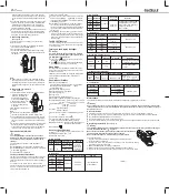
F. Measuring Frequency
(See Figure 7)
To measure frequency and duty cycle, connect the
Meter as follows:
Red
Black
Hz
a. Insert the red test lead into the
Hz
terminal and the
black test lead into the
COM
terminal.
b. Set the rotary switch to Hz.
c. Connect the test leads across with the object being
measured. The measured frequency value shows on
the display.
When frequency and duty cycle measurement has
been completed, disconnect the connection between
the testing leads and the circuit under test, and remove
the testing leads away from the input terminals of the
Meter.
Note
G. Measuring Temperature
( See Figure 8)
1. Insert the red temperature
probe into the
C
terminal
and the black temperature
probe into the
COM
terminal.
o
o
o
2. Set the rotary switch to
C
.
.
3. Place the temperature
probe to the object being
measured.
The measured value shows on
the display.
Red
Black
Figure 8
To measure temperature, connect the Meter as follows:
When there is no temperature probe
inserted into the terminals, the LCD displays
OL
.
The included point contact temperature probe can only
be used up to 250 C.For any measurement higher than
that, it is necessary to use another type of temperature
probe.
Note
When temperature measurement has been completed,
disconnect the connection between the temperature
probe and measured object, and remove the tempera
-ture probe from the input terminals of the Meter.
Operation of Hold Mode
To avoid possibility of electric shock, do not use
Hold mode to determine if circuits are without power.
The Hold mode will not capture unstable or noisy
readings.
Warning
The Hold mode is applicable to all measurement
functions.
Press
HOLD
to enter Hold mode; the Meter beeps.
Press
HOLD
again or turn the rotary switch to exit Hold
mode; the Meter beeps.
In Hold mode,
is displayed.
The REL mode applies to all measurement functions
except frequency and duty cycle. It subtracts a stored
value from the present measurement value and displays
the result.
For instance, if the stored value is 20.0V and the
present measurement value is 22.0V, the reading would
be 2.0V. If a new measurement value is equal to the
stored value then display 0.0V.
To enter or exit REL
mode:
Use rotary switch to select the measurement function
before selecting
REL
. If measurement function
changes manually after
REL
is selected, the Meter
exits the REL mode.
Press
REL
to enter REL mode, auto ranging
turns off, and the present measurement range is
locked and stored as the stored value. All the measure
-ments done after will be automatically subtract this
stored value.
Press
REL
again to exit REL mode and return
to common measurement mode.If you want to enter
the auto ranging measurement mode or other ranges,
please turn the rotary switch or power off the Meter
and start again.
The Use of Relative Value Mode
The SELECT Button
It uses for selecting the required measurement function
when there is more than one function at one position
of the rotary switch.
Turning on the Display Backlight
In order to avoid the hazard arising from mistaken
readings in insufficient light or poor vision, please
use Display Backlight function.
Warning
Press and hold button for over 2 seconds to turn
the Display Backlight on.
Press button again to turn the Display Backlight
off, otherwise it will stay on continuously.
To preserve battery life, the Meter automatically turns
off if you do not turn the rotary switch or press any button
for around 15 minutes.
Sleep Mode
The Meter can be activated by turning the rotary switch
or press
ing the effective
button, it will return to
working mode.
Maximum Voltage between
any Terminals and Grounding: 600V rms or 600V DC.
Maximum Current Measurement: 1000A.
of Transformer Jaw:
Maximum Jaw Opening:
40mm.
Maximum Display: Digital: 3999
Overload Display: OL
Range: Auto
Polarity Display: Negative display: “-“
Measurement Speed: Updates 3 times/second.
Temperature: Operating: 0
o
C to +40
o
C (32
o
F to+104
o
F).
Storage: -10
o
C to +50
o
C (14
o
F to +122
o
F).
Relative Humidity: 75% @ 0
o
C to 40
o
C
;
70% @ -10 to 50
o
C
.
Altitude: Operating: 2000 m.
Storage: 10000 m.
General Specifications
Battery Type: One piece of 9V (NEDA1604 or 6F22
or 006P).
Low Battery Indication
:
Display
Dimensions (HxWxL): 236mm x 97mm x 40mm
Weight: Approximate 350g (battery included).
Safety/Compliances: IEC61010 CAT. II 600V / CAT III
300V and Double Insulation.
Certifications:
Accuracy: (a% r b digits), guarantee for 1 year.
Operating temperature: 23
o
C 5
o
C .
Relative humidity: 75%.
Accuracy Specifications
A. AC Current
Range Resolution Accuracy Remarks
400A
1000A
0.1A
1A
(1.5%+5)
800A
(2%+5)
Frequency resp
-onse 50Hz~
60Hz.Display
RMS value of
sine wave(mean
value response).
>800A (3%+5)
B. DC Voltage
400mV
4V
40V
400V
600V
100 V
1mV
10mV
100mV
1V
(0.8%+3)
(0.8%+1)
(1%+3)
Range
600V DC
600V AC
Input impedance:
around 10M .
Resolution Accuracy Overload Protection
Remarks
C. AC Voltage
4V
40V
400V
600V
(1.2%+2)
600V DC
600V AC
Range Resolution Accuracy Overload
Protection
Remarks
1mV
10mV
100mV
1V
(1.5%+5)
Input impedance around 10M .
Displays RMS value of sine
wave (mean value response).
Frequency response:
40Hz ~ 400Hz.
D. Resistance
Range Resolution Accuracy Overload Protection
400
4k
0.1
1
(1%+2)
500V DC or AC
(1.2%+5)
40k
400k
4M
40M
10
100
1k
10k
500V DC or AC
(1%+2)
(1.2%+2)
(1.5%+2)
E. Diode and Continuity Test
Function Range Resolution Overload Remarks
Diode
Continuity
1mV
0.1
500V DC or AC
Displays the nearest value
of forward voltage drop
Buzzer beeps when
100
F. Frequency (auto-ranging)
Range Resolution Accuracy Overload Protection Remarks
10Hz-
10MHz
Min
0.001Hz
(0.1%+3)
500V DC or VAC
Amplitude a:
1MHz: 300mV rms a 30V rms;
1MHz: 600mV rms a 5V rms
G.
T
emperature
-40
o
C~0
o
C
1
o
C~400
o
C
401
o
C~1000
o
C
Range Resolution Accuracy Overload Protection
1
o
C
(4%+4)
(2%+8)
(3%+10)
500V DC or AC
Maintenance
This section provides basic maintenance information including battery replacement instruction.
Do not attempt to repair or service your Meter unless you are qualified to do so and have the relevant calibr
-ation, performance test, and service information.To avoid electrical shock or damage to the Meter, do you get
water inside the case.
Warning
A. General Service
Periodically wipe the case with a damp cloth and mild detergent. Do not use abrasives or solvents.
To clean the terminals with cotton bar with detergent, as dirt or moisture in the terminals can affect readings.
Turn the Meter to
OFF
position when it is not in use.
Take out the battery when it is not using for a long time.
Do not use or store the Meter in a place of humidity, high temperature, explosive, inflammable and strong magnetic field.
B. Replacing the Battery
(See Figure 9)
Warning
Figure 9
To avoid false readings, which could lead to possible electric shock or personal injury,replace the battery as
soon as the battery indicator “ ” appears.
Make sure the transformer jaw and the test leads are disconnected from
the circuit being tested before opening the case bottom.
Make sure the test leads are removed from the input terminals.
Screw
To replace the battery:
1. Turn the rotary switch of the Meter to
OFF
position and remove all the
connections from the terminals.
2. Remove the screw from the battery compartment, and separate the battery
compartment from the case bottom.
3. Remove the battery from the battery compartment.
4. Replace the battery with a new 9V battery (NEDA1604, 6F22 or 006P) .
5. Rejoin the case bottom and battery compartment, and reinstall the screw.
** END **
P/N: XX
JAN.2019. REV. 0