Gator
www.gatorcn.com China
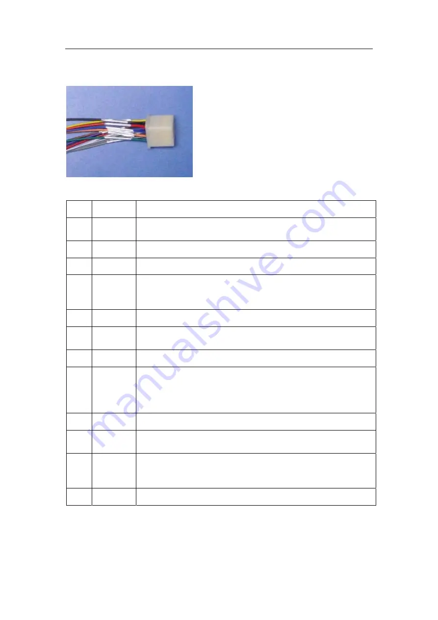
4.2
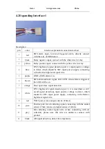
Expanding Interface 1
Description
pin
color
function explanation/connection method
1
red
SOS alarm input, low-level triggered alarm, directly connect
with the wire of SOS button
2
black
Relay negative input, connect with the white wire in relay
3
yellow
Relay positive input, connect with the yellow wire in relay
4
blue
HV2( high-level signal detection port 2,) input positive voltage
to detect, which should be 5DC~input power supply, connecting
with effective high-level signal wire.
5
purple
GND of SOS alarm wire
6
brown
SOS alarm indicator signal, drive LED, when alarm is triggered,
the LED will be on.
7
orange
Door open/close signal detection.
8
white
HV1( high-level signal detection port 1, it is described as A/C
on/off signal detection), input positive voltage to detect, which
should be 5DC~input power supply, connecting with effective
high-level signal wire.
9
red
5VDC power (max output current: 220mA)
10 green
Positive pole for oil collecting signal, connecting with the added
sensor of fuel volume or original sensor of vehicle
11
grey
Oil collecting control signal wire (when connecting with oil
collector), please note: this wire are unable to connect with
ground.
12
black
AD signal detection, detect the temperature.


