background image

20          Maintaining and Troubleshooting the Gateway ALR 7300 Server

Expansion slots

The system features seven expansion slots: five PCI slots, one shared 
PCI/RAID port slot, and one shared PCI/ISA slot. The I

2

O feature 

connector is aligned with one of the PCI slots (secondary PCI slot 1). If you 
install a card in the I

2

O feature connector, you may not be able to use the 

corresponding PCI slot.

The PCI bus processes peripheral transactions at a system clock speed of up 
to 33 MHz.

I/O connectors

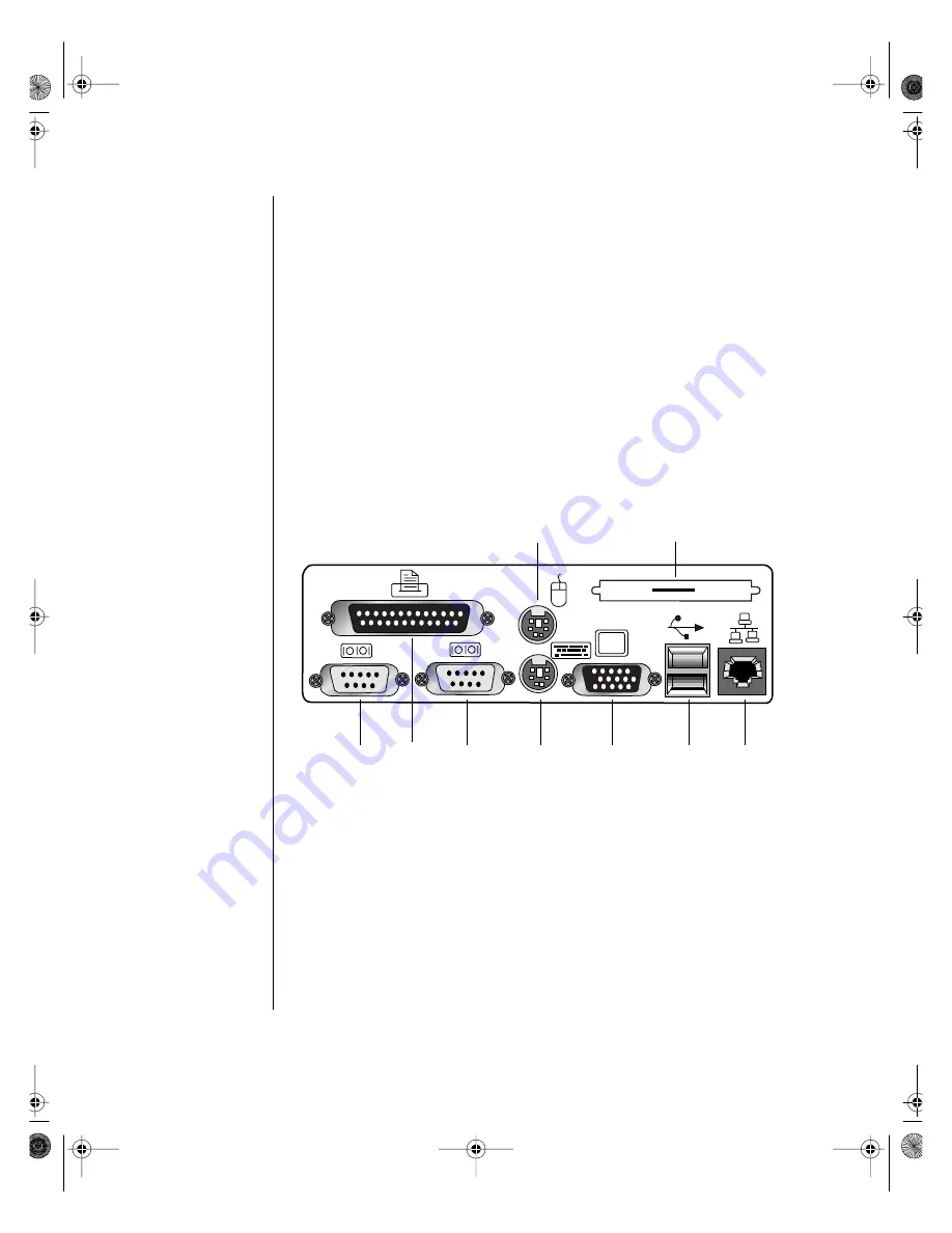
The I/O connectors are located on the back cover of the system. Figure 8 
shows the connectors.

Figure 8: I/O Connectors

The following I/O connectors are included with the system:

Two universal serial bus (USB) ports provide connection for a 
growing list of peripherals including mouse, keyboard, joystick, 
monitor, tape, and diskette drives. You can daisy-chain up to 127 
devices from each port. The port also provides hot-swap capability 

Parallel 
port

Serial 
port 1

Serial 
port 2

Mouse 
port

Keyboard 
port

Video 
port

Dual USB 
ports

RJ-45 
ethernet 
port

Punchout section for 
optional external SCSI

4075.book  Page 20  Friday, April 2, 1999  9:26 AM

Содержание ALR 7300

Страница 1: ...Maintaining and Troubleshooting the Gateway ALR 7300 Server Part 8504075 A MAN SYS US 7300 TECH REF R1 12 98 4075 book Page 1 Friday April 2 1999 9 26 AM...

Страница 2: ...Inside logo and Pentium are registered trademarks and MMX is a trademark of Intel Corporation Microsoft MS MS DOS and Windows are trademarks or registered trademarks of Microsoft Corporation All othe...

Страница 3: ...lacing the top cover 8 Replacing the bezel 9 Replacing the side panel 10 Components 11 System board components 12 Chassis fans 14 Power connectors 14 Drive controllers and connectors 15 Front panel co...

Страница 4: ...etWare 4 11 drivers and Seagate Backup Exec issues 59 BIOS Setup 61 About the BIOS Setup Utility 62 Using the BIOS Setup Utility 62 Main menu screen 63 Advanced menu screen 67 Security menu screen 76...

Страница 5: ...106 Specifications 109 Memory map 110 I O map 111 IRQ usage 112 DMA usage 113 DIMM configurations 114 Regulatory compliance statements 116 FCC Notice 116 Industry Canada Notice 116 CE Notice 117 VCCI...

Страница 6: ...iv Maintaining and Troubleshooting the Gateway ALR 7300 Server 4075 book Page iv Friday April 2 1999 9 26 AM...

Страница 7: ...Preface Conventions used in this guide vi Safety instructions vii Additional information sources viii 4075 book Page v Friday April 2 1999 9 26 AM...

Страница 8: ...that the keys must be pressed simultaneously Setup Commands to be entered options to select and messages that appear on your monitor are printed in bold User s Guide Names of publications and files a...

Страница 9: ...ter ventilation slots Use the voltage setting for your area The voltage selector switch is set at the factory to the correct voltage As a safety feature this system is equipped with a 3 wire power cor...

Страница 10: ...rating instructions are followed The system was dropped or the cabinet is damaged The system s performance changes Additional information sources Along with this manual and your user s guide you can f...

Страница 11: ...1 Chapter 1 System Access Static electricity precautions 2 Opening the system 3 Closing the system 8 4075 book Page 1 Friday April 2 1999 9 26 AM...

Страница 12: ...atic causing surfaces such as plastic and styrofoam in your work area Remove the parts from their antistatic bags only when you are ready to use them Do not lay parts on the outside of antistatic bags...

Страница 13: ...ugh the side panel 1 Follow the ESD precautions described in Static electricity precautions on page 2 2 Turn off the system and disconnect the power cord 3 Remove the two screws that secure the side p...

Страница 14: ...Removing the Side Panel 4 Pull the cover toward the back of the system and remove it from the chassis 5 Set the side cover aside 6 If you need to remove the other side panel repeat steps 3 5 for the...

Страница 15: ...described in Static electricity precautions on page 2 2 Turn off the system and disconnect the power cord 3 Remove both side panels as described in Removing the side panel on page 3 4 From the inside...

Страница 16: ...sis 1 Follow the ESD precautions described in Static electricity precautions on page 2 2 Turn off the system and disconnect the power cord 3 Remove side panel as described in Removing the side panel o...

Страница 17: ...System Access 7 Figure 3 Removing the Top Cover 6 Pull the top cover straight up 7 Set the cover aside 4075 book Page 7 Friday April 2 1999 9 26 AM...

Страница 18: ...ve removed the top cover to access components at the top of the system replace the top cover before replacing other covering pieces 1 Align the top cover with the ledges on the chassis See Figure 4 Fi...

Страница 19: ...re aligned with the mount holes on the front of the chassis See Figure 5 Figure 5 Replacing the Front Bezel 2 Insert the bezel pegs into the correct holes at the top of the chassis 3 Swing the bottom...

Страница 20: ...panel 1 Align the side panel with the ledges on the chassis 2 Slide the panel toward the front of the chassis see Figure 6 Figure 6 Reinstalling the Side Panel 3 Secure the panel with the screws you...

Страница 21: ...2 Chapter 2 Components System board components 12 Quick Hot swap RAID cage 22 SCSI backplane components 23 4075 book Page 11 Friday April 2 1999 9 26 AM...

Страница 22: ...peripherals See the table below for the key to Figure 7 Figure 7 System Board A Chassis fan 1 connector B Power connector C Supplemental power connector D Soft power connector E Power supply power fau...

Страница 23: ...ernal boot ROM connector X External I2 C connector Y SCSI B connector Z SCSI A connector AA Clear CMOS jumper AB Battery AC ISA slot 1 shared with secondary PCI slot 4 AD Secondary PCI slot 4 shared w...

Страница 24: ...nnectors on the system board These connectors provide power for cooling fans that may be positioned in several parts of the chassis to cool critical components Power connectors There are several power...

Страница 25: ...7300 Drive controllers and connectors There are several controllers and connectors for the control of the various drives that are or can be installed in the system Hard drive IDE controller and conne...

Страница 26: ...e SCSI configuration supporting up to 15 connected SCSI peripherals per channel for a total of up to 30 devices Up to seven 8 bit devices can be installed on each channel Multithreading support for up...

Страница 27: ...o allow hard drive activity and system monitoring to recognize the external drive Hard drive LED connector This connector allows you to connect all of the hard drives to the hard drive activity LED on...

Страница 28: ...nagement connector allows you to connect a server management device to the system board to monitor system activities Cover intrusion switch connector Connects a cover intrusion switch to the system bo...

Страница 29: ...Clearing CMOS memory returns all BIOS Setup settings to the default values CPU speed setting jumper This jumper allows you to set the speed of the processor Both processors in dual processor configura...

Страница 30: ...up to 33 MHz I O connectors The I O connectors are located on the back cover of the system Figure 8 shows the connectors Figure 8 I O Connectors The following I O connectors are included with the syst...

Страница 31: ...he following paragraphs Processors and processor slots Depending on the model the system is equipped with one Intel Pentium II Xeon processor with 512 KB 1 MB or 2 MB ECC L2 cache integrated into a si...

Страница 32: ...he necessary hardware to install it in the system Each cage supports three one inch high 3 5 inch SCA SCSI drives For optimum operation use only approved RAID ready drives in the RAID Cage The RAID Ca...

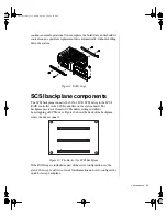
Страница 33: ...e SCSI RAID controller or the SCSI controllers on the system board The backplane provides automatic SCSI address setting and allows hot swapping of SCSI drives Figure 10 shows the back of the backplan...

Страница 34: ...24 Maintaining and Troubleshooting the Gateway ALR 7300 Server 4075 book Page 24 Friday April 2 1999 9 26 AM...

Страница 35: ...alling Components Replacing the processor 26 Installing a second processor 30 Setting the jumpers 33 Installing memory and hardware 35 Installing software and drivers 58 4075 book Page 25 Friday April...

Страница 36: ...kits contact one of the sources listed in the Assistance Resources document 1 Turn off the system and disconnect the power cord 2 Open the case Opening the system on page 3 observing the static elect...

Страница 37: ...Installing Components 27 Figure 11 Removing the Lock Bar 4 Lift the cartridge up and away from the system board See Figure 12 4075 book Page 27 Friday April 2 1999 9 26 AM...

Страница 38: ...ssor cartridge that you removed in a safe place 6 Remove the replacement processor cartridge from its protective wrapping and place it in the cartridge supports for the slot 2 connector 7 Slide the ca...

Страница 39: ...came with the processor upgrade kit 9 Replace the lock bar on the processor support and secure it with the two screws that you removed in Step 3 10 Set the jumpers for the new processor configuration...

Страница 40: ...or overheats and fails if it is not cooled sufficiently The heat sink provided with the processor on the system provides all necessary cooling for the processor For the latest details on the availabil...

Страница 41: ...mponents 31 Figure 14 Removing the Terminator Card 5 Align the new Pentium II Xeon SEC cartridge into the CPU 2 connector and press it firmly into place See Figure 15 4075 book Page 31 Friday April 2...

Страница 42: ...ing the two screws you removed in Step 3 7 Set the jumpers for the new processor configuration see the section Setting the jumpers on page 33 8 Insert the VRM into the connector provided until the rel...

Страница 43: ...processor you may need to change jumper settings The Processor Speed jumper JP22 configuration block lets you set the processor speed The system automatically detects the bus speed supported by the pr...

Страница 44: ...the Clear CMOS jumper JP15 to connect pins 2 and 3 6 Reconnect the power cord and turn on the system Wait until the system boots and you see the message that confirms the CMOS memory has been cleared...

Страница 45: ...ct the power cord 2 Open the case Closing the system on page 8 observing the static electricity precautions in Static electricity precautions on page 2 3 Pull open the socket clamps on each side of th...

Страница 46: ...e case as described in Closing the system on page 8 7 Reconnect the power cord and turn on the system 1 Gently push out the plastic socket clamps on each end of the DIMM The DIMM should pop up slightl...

Страница 47: ...bay The 3 5 inch drives are secured to a metal mounting bracket which enables easy installation and removal from the system chassis This bracket supports a 3 5 inch diskette drive which was installed...

Страница 48: ...es after you install the new drive 5 Remove the screws securing the drive bracket to the system chassis and remove the drive bracket from the chassis Doing so also removes the 3 5 inch metal filler pa...

Страница 49: ...inch Drive 7 Place the new 3 5 inch drive in the mounting bracket see Figure 22 Figure 22 Installing the New 3 5 inch Drive 8 Secure the drive to the mounting bracket using the screws you removed in S...

Страница 50: ...Figure 23 Replacing the Drive Bracket 10 Secure the drive bracket to the chassis with the screws you removed in Step 5 11 Connect the power and data cables to the 3 5 inch drive making sure the cables...

Страница 51: ...is installed in the drive bay remove the metal drive bay cover from the front of the 5 25 inch drive bay Also remove the plastic drive bay cover on the front bezel 5 If you are replacing an existing...

Страница 52: ...emove the rails 8 Mount the guide rails to the new drive using the screws you removed from the old drive 9 Align the guide rails with the rail guides in the drive bay and slide the drive all of the wa...

Страница 53: ...ble orientation 11 Close the case as described in Closing the system on page 8 12 Reconnect the power cord and turn on the system 13 Run the configuration software that came with the drive if required...

Страница 54: ...Each cage supports three drives Begin cage installation from the bottom drive bay Figure 26 Hot Swap Drive Cage 1 Remove the side panel as described in Removing the side panel on page 3 2 Disconnect...

Страница 55: ...ive in a safe place preferably in an anti static bag D Repeat steps a c for all drives in the drive cage 4 Remove the old RAID Cage by pressing the tabs on the slide rails toward the center of the cag...

Страница 56: ...oubleshooting the Gateway ALR 7300 Server Figure 28 Removing the RAID Cage 1 Slide the new drive cage into the drive bracket as shown in Figure 29 Installing the New RAID Cage 4075 book Page 46 Friday...

Страница 57: ...onnect all cables that connect the RAID Cage and its backplane to other system components 3 Reinstall the SCSI drives in the new RAID cage by aligning the rails and sliding them all the way into the c...

Страница 58: ...at the front of the chassis 1 Turn off the system and disconnect the power cord 2 Open the case Opening the system on page 3 observing the static electricity precautions in Static electricity precaut...

Страница 59: ...attach the hard disk mounting bracket to the chassis and remove the bracket from the chassis see Figure 31 Figure 31 Removing the Hard Disk Bracket and Drive 6 Remove the screws that attach the hard d...

Страница 60: ...ables to the hard drive making sure the cables match their original position See the drive documentation for proper drive jumper settings and cable orientation 10 Close the case as described in Closin...

Страница 61: ...screwdriver remove the punchout section insert the blade of the screwdriver into the slot in the punchout then pry back and fourth until loose Figure 33 Installing the SCSI Cable Kit 6 One end of the...

Страница 62: ...xpansion slots are designed to allow the slot to be shared with a special purpose expansion card such as a RAIDport card Some ISA expansion cards have jumpers or switches that set interrupts and I O a...

Страница 63: ...to the card see card documentation for proper jumper settings and cable orientation 9 Close the case as described in Closing the system on page 8 10 Reconnect the power cord and turn on the system It...

Страница 64: ...owing all static electricity precautions as described in Static electricity precautions on page 2 3 If necessary disconnect any cables connected to the expansion card 4 Remove the screw that secures t...

Страница 65: ...se button on the card guide to return the retaining latch to the extended position 8 Place an expansion port cover over the empty slot and secure it with the screw you removed earlier 9 Replace the co...

Страница 66: ...case Opening the system on page 3 observing the static electricity precautions in Static electricity precautions on page 2 5 Locate the battery on the system board see Figure 7 on page 14 The battery...

Страница 67: ...ery installation If you have problems after installing the new battery try each of the items listed below replacing the cover and restarting the computer after each try Turn off the system and ensure...

Страница 68: ...specific to the operating system you run on the system However some tips on installing drivers or other software in critical situations or under particular circumstances are provided below Installing...

Страница 69: ...start the server and the second on board SCSI driver will load successfully 2 During the NetWare installation select SMP support a message to install an unlisted PSM file will display Path to the loca...

Страница 70: ...60 Maintaining and Troubleshooting the Gateway ALR 7300 Server 4075 book Page 60 Friday April 2 1999 9 26 AM...

Страница 71: ...4 Chapter 4 BIOS Setup About the BIOS Setup Utility 62 Using the BIOS Setup Utility 62 Updating the BIOS 81 4075 book Page 61 Friday April 2 1999 9 26 AM...

Страница 72: ...ould have no trouble getting the information that you need Using the BIOS Setup Utility The computer BIOS has a built in setup utility that lets you configure several basic system characteristics The...

Страница 73: ...hat sub menu Setup Defaults Press F9 to set the setup parameters to their factory default values A submenu appears asking you to press either ENTER to load the defaults or ESC to skip Save Exit Press...

Страница 74: ...ter hard disk drive Details of this screen are provided in the section Hard disk drive setup screen on page 65 Primary Slave opens the Primary Slave screen to permit you to setup the primary slave har...

Страница 75: ...where you can enter the Cylinders Heads Sectors and Maximum Capacity of the drive you are configuring These values are generally available from the documentation for the drive or the drive label itse...

Страница 76: ...abled and Disabled 32 Bit I O enabling this option allows 32 bit communication between the processor and the IDE controller The options are Enabled and Disabled Transfer Mode selects the method for mo...

Страница 77: ...and No Reset Configuration Data selecting Yes causes the system to clear its configuration data and automatically configure all PnP devices at bootup Selecting No causes the system to use the existin...

Страница 78: ...n are provided in the section Keyboard features screen on page 74 Cache Memory opens the Cache Memory Configuration screen Details of this screen are provided in the section Cache memory screen on pag...

Страница 79: ...rce Configuration Screen Memory Reservation opens the Memory Reservation screen This screen allows you to reserve blocks of upper memory for use by legacy ISA devices Details of this screen are provid...

Страница 80: ...e blocks of memory for ISA devices Figure 43 Memory Reservation Screen XXXX XXXX the specified area of upper memory may be reserved for use by legacy ISA devices Options are Available and Reserved IRQ...

Страница 81: ...BIOS Setup 71 Figure 44 IRQ Reservation Screen IRQx the specified IRQ may be reserved for use by legacy ISA devices Options are Available and Reserved 4075 book Page 71 Friday April 2 1999 9 26 AM...

Страница 82: ...the base I O address for integrated Serial Port A Using the or key displays the optional addresses available Interrupt displays the current interrupt for integrated Serial Port A Using the or key dis...

Страница 83: ...O address for the integrated Parallel Port Using the or key displays the optional addresses available Interrupt displays the current interrupt for the integrated Parallel Port Using the or key displa...

Страница 84: ...M LOCK key Key Click options are Enabled and Disabled Enable causes an audible click when each key is pressed Keyboard Auto Repeat Rate determines the rate at which a character repeats if a key is hel...

Страница 85: ...a controls the caching of the system BIOS area Options are Uncached or Write Protect Cache Video BIOS Area controls the caching of the video BIOS area Options are Uncached or Write Protect Cache Base...

Страница 86: ...d Write Back MSCS Support Options are Enabled and Disabled Enable to support Microsoft Cluster Security menu screen This screen allows you to set system security characteristics Figure 48 Security Men...

Страница 87: ...at boot If the user password has already been set you must enter the current password before you are able to enter and verify a new password Password on Boot when this option is enabled the system pr...

Страница 88: ...k Boot Second Boot Device designates the device that the system polls second upon boot up assuming that it finds no boot data on the previously designated device Options include Diskette Drive Hard Dr...

Страница 89: ...Hard Drive displays a list of available hard drives The system attempts to boot to the operating system from the first hard drive on this list If no operating system is found the system tries the nex...

Страница 90: ...ings you have entered The next time you boot the system the BIOS configures your system using the old settings Load Setup Defaults displays the setup defaults in cases where the settings have been cor...

Страница 91: ...d restart the system with the disk in the drive 7 At the prompt type PROGGTW and press ENTER 8 The system asks you if you want to change the BIOS Press Y and then press ENTER 9 Once the BIOS files hav...

Страница 92: ...82 Maintaining and Troubleshooting the Gateway ALR 7300 Server 4075 book Page 82 Friday April 2 1999 9 26 AM...

Страница 93: ...Troubleshooting checklist 85 CD ROM problems 87 Hard disk problems 88 Memory Processor problems 89 Modem problems 90 Peripheral Adapter problems 91 Printer problems 93 System problems 94 Video problem...

Страница 94: ...use the system to beep or display messages or images on the screen Other viruses are highly destructive and corrupt or erase the contents of files or disks To be safe never assume any virus is harmles...

Страница 95: ...es and always scan new software for any viruses prior to installing files If the system has been infected find and remove the viruses using an anti virus program Then turn off the system for a minimum...

Страница 96: ...disconnected stored energy within the components can cause a painful or harmful shock If a peripheral such as the keyboard mouse drive or printer does not appear to work verify that all connections ar...

Страница 97: ...he volume control The speakers may be muted via the Multimedia volume control From the Accessories menu Start Programs Accessories click Multimedia and then click Volume Control Make certain the volum...

Страница 98: ...hnical Support The secondary IDE device may be disabled Restart your computer and then press F2 to enter the setup program From the Peripheral Configuration Advanced menu set the Secondary IDE Interfa...

Страница 99: ...properly Open the system and reseat the drive controller This possibility is only valid for systems that include an add in drive controller Probable Cause Solution Memory was added or removed and the...

Страница 100: ...inspect it for damage If a pin is bent very carefully try to straighten it Probable Cause Solution The modem has not been added as new hardware Add the modem as new hardware The modem is not connected...

Страница 101: ...ast device on the SCSI chain is terminated The device cables are not installed correctly Open the system and check all cables between the controller and the device Probable Cause Solution The diskette...

Страница 102: ...closed unprotected Probable Cause Solution The diskette is corrupted Remove the diskette from the drive If the light remains on try restarting the system The cable to the drive is not connected proper...

Страница 103: ...er and the system Make certain it is connected to the proper port Check the connector and cable for bent or broken pins The printer is not designated as the default printer If the printer to which you...

Страница 104: ...y plugged into their AC in connectors on the back panel of the computer Verify that both power supplies are set to the correct voltage range 115 V AC or 230 V AC Verify that both power supplies are tu...

Страница 105: ...ata cable is not connected Make certain the monitor data cable is connected to the video controller on the back of the system The connector or cable is damaged Check the connector and cable for bent o...

Страница 106: ...ned on and then restart the system The display type is set incorrectly From the Control Panel window Start Settings Control Panel double click Display set the display to the appropriate monitor type a...

Страница 107: ...uninterruptible power supply UPS is damaged Disconnect the monitor power cable and connect it directly to the power source The monitor is too close to a source of electrical interference Move the mon...

Страница 108: ...ation is incorrect Enter BIOS Setup and verify the values CD ROM is not recognized See The CD ROM drive is not recognized by the system on page 88 Data error Run ScanDisk on the reported disk Decreasi...

Страница 109: ...ent disk space Check the free space on the disk volume If the volume is full or almost full remove unnecessary files Invalid configuration information Enter BIOS Setup and verify the values Invalid pa...

Страница 110: ...s Not enough memory Close all programs that are not currently in use Print queue is full Wait until the current print job has completed before sending another print job If you receive this error often...

Страница 111: ...yms and abbreviations 102 Terms and definitions 106 Specifications 109 Memory map 110 I O map 111 IRQ usage 112 DMA usage 113 DIMM configurations 114 Regulatory compliance statements 116 4075 book Pag...

Страница 112: ...Basic input output system BIST Basic integrity self test CD Compact disc CD ROM Compact disc read only memory CHS Cylinder head sector CMOS Complementary metal oxide semiconductor CPU Central process...

Страница 113: ...l area network LBA Logical block addressing LED Light emitting diode LVD Low voltage differential MB Megabyte MBE Multiple bit error Mbps Megabits per second MIDI Musical instrument digital interface...

Страница 114: ...rpm Revolutions per minute RTC Real time clock SBE Single bit error SCA Single connector attachment SCI Signal control interrupt SCSI Small computer system interface SDRAM Synchronous dynamic random a...

Страница 115: ...Reference Data 105 USB Universal serial bus V Volt V AC Volts alternating current VGA Video graphics array VRM Voltage regulator module W Watt 4075 book Page 105 Friday April 2 1999 9 26 AM...

Страница 116: ...oot you reset the computer when it is already turned on Boot disk A disk containing operating system programs required to start your computer A boot disk can be a diskette hard drive or CD Byte The ba...

Страница 117: ...he device needs the processor s services The number of IRQs is limited by industry standards Operating system A program that supervises the computer s operation including handling I O networking and c...

Страница 118: ...esolution is measured by the number of pixels the screen can display For example a resolution of 800x600 means that the screen can display 800 pixels in a row and can display 600 rows The more pixels...

Страница 119: ...nd a full complement of I O ports Dimensions 21 38 H x 9 25 W x 19 38 D 46 lbs Processor Intel Pentium II Xeon processor Processor speed 400 or 450 MHz Processor upgrade Slot 2 Cache subsystem 512 KB...

Страница 120: ...buffer 768 KB 896 KB 000C 0000 000D FFFF 128 KB Reserved for ROM on I O adapters 896 KB 1024 KB 1 MB 000E 0000 000F FFFF 128 KB System BIOS ROM Above 1 MB 1 MB 16 MB 0010 0000 00FF FFFF 15 MB Extended...

Страница 121: ...mmand mode register 0048 1 byte Programmable interval timer 2 0049 1 byte Reserved 004A 1 byte CPU speed control counter 2 004B 1 byte Command mode register 0061 0070 16 bytes NMI status registers 008...

Страница 122: ...use by add on devices IRQ Resource NMI 0 System timer 1 Keyboard 2 Cascade 3 Serial port 2 COM2 4 Serial port 1 COM1 5 Secondary parallel port LPT2 6 Diskette controller 7 Primary parallel port LPT1...

Страница 123: ...ccess DMA channels that the system typically uses and which ones are available for use by expansion cards DMA Resource 0 Cascade 1 Available 2 Floppy controller 3 Available 4 Redirect cascade 5 Availa...

Страница 124: ...2 x 72 16 MB 2 x 72 16 MB 128 MB 8 x 72 64 MB 4 x 72 32 MB 4 x 72 32 MB 128 MB 8 x 72 64 MB 8 x 72 64 MB 128 MB 16 x 72 128 MB 192 MB 8 x 72 64 MB 8 x 72 64 MB 4 x 72 32 MB 4 x 72 32 MB 192 MB 8 x 72...

Страница 125: ...512 MB 64 x 72 512 MB 576 MB 64 x 72 512 MB 8 x 72 64 MB 704 MB 64 x 72 512 MB 16 x 72 128 MB 8 x 72 64 MB 960 MB 64 x 72 512 MB 32 x 72 256 MB 16 x 72 128 MB 8 x 72 64 MB 1 GB 32 x 72 256 MB 32 x 72...

Страница 126: ...er Connect the equipment into an outlet on a circuit different from that to which the receiver is connected Consult the dealer or an experienced radio TV technician for help This equipment has been te...

Страница 127: ...00 4 3 1996 EN 61000 4 4 1988 or IEC 801 4 1998 EN 61000 4 5 1995 EN 61000 4 6 1996 EN 61000 4 8 1993 EN 61000 4 11 1994 ii Low Voltage Directive Safety 73 23 EEC as per EN 60950 1992 A1 A2 A3 A4 and...

Страница 128: ...has been tested and found to comply with the limits for a Class A digital device pursuant to the Australian New Zealand standard AS NZS 3548 set out by the Spectrum Management Agency Caution Disconnec...

Страница 129: ...Serial Port A 72 Base I O Address field Serial Port B 72 boot disk write protection 77 boot menu screen 78 C800 CBFF field 70 Cache Base 0 512K field 75 Cache Base 512K 640K field 75 Cache C800 CBFF f...

Страница 130: ...Repeat Rate field 74 Keyboard Features field 68 screen 74 Large Disk Access Mode field 68 LBA Mode Control field 66 Legacy Diskette A field 64 Legacy Diskette B field 64 Load Setup Defaults field 80...

Страница 131: ...d 76 Cache CC00 CFFF Setup utility field 76 Cache D000 D3FF Setup utility field 76 Cache D400 D7FF Setup utility field 76 Cache D800 DBFF Setup utility field 76 Cache DC00 DFFF Setup utility field 76...

Страница 132: ...3 DMA usage 113 E Embedded PCI NIC Setup utility field 69 Embedded PCI SCSI Channel A Setup utility field 68 Channel B Setup utility field 68 error messages 98 Exit Discarding Changes Setup utility fi...

Страница 133: ...x Setup utility field 71 J jumpers clear CMOS 34 processor bus speed 33 setting 33 K Key Click Setup utility field 74 KeyboardAuto RepeatDelay Setup utility field 74 Keyboard Auto Repeat Rate Setup ut...

Страница 134: ...bleshooting 91 Plug and Play O S Setup utility screen 67 power supply connectors system board 14 primary master drive Setup screen 65 Primary Master Setup utility field 64 primary slave drive Setup sc...

Страница 135: ...ity field 72 Serial Port B Setup utility field 72 Set Supervisor Password Setup utility field 77 Set User Password Setup utility field 77 setting jumpers 33 Setup 32 Bit I O 66 advanced menu screen 67...

Страница 136: ...Repeat Rate 74 Keyboard Features 68 keyboard features screen 74 keys used 62 Large Disk Access Mode 68 LBA Mode Control 66 Legacy Diskette A 64 Legacy Diskette B 64 Load Setup Defaults 80 main menu s...

Страница 137: ...12 memory map 110 opening 3 specifications 109 troubleshooting 94 system board features 12 I O connectors 20 illustration 12 System Date Setup utility field 64 System memory Setup utility field 64 Sys...

Страница 138: ...aSCSI controller 16 updating BIOS 81 Use Multiprocessor Specification Setup utility field 67 User Password Setup utility field 76 using IRQ resources 112 Setup 62 V VCCI Notice 117 video troubleshooti...

Отзывы: