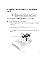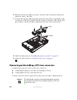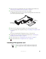
93
www.gateway.com
6
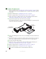
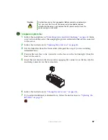
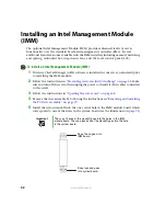
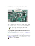
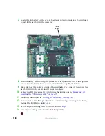
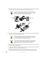
Find the IMM connector on the left back portion of the system board.
7
Grasp the module board by the edges, close to the mounting connector, align the
board with the IMM connector on the system board, then gently apply pressure to
seat the module.
Make sure the module is fully seated and the nylon standoff is inserted into the
corresponding hole in the system board.
8
Replace the riser assembly by following the instructions in
the PCI riser assembly” on page 79
.
9
Follow the instructions in
“Closing the server case” on page 46
10
Following the installation of a new IMM module, you must reinstall the GSM software
(supplied on a CD with your server) and update the FRU/SDR (see
). When you subsequently reboot your server, the GSM software
will take over management of the server.
Caution
Exercise extreme caution when installing the IMM module. The
module is fragile and can be damaged easily.
IMM connector
Hole for standoff
Содержание 9515
Страница 1: ...User Guide Gateway 9515 Server ...
Страница 5: ...iv www gateway com B BIOS Settings 155 C Safety Regulatory and Legal Information 173 Index 181 ...
Страница 15: ...10 www gateway com ...
Страница 125: ...120 www gateway com ...
Страница 151: ...146 www gateway com ...
Страница 177: ...172 www gateway com ...
Страница 178: ...Appendix C 173 Safety Regulatory and Legal Information Safety information Legal and Regulatory Information ...
Страница 193: ...188 www gateway com ...
Страница 194: ...A MAN 9515 USR GDE R0 12 04 ...

