Magnum 4K24 Switches Installation and User Guide (10/04)
21
www GarrettCom com
.
.
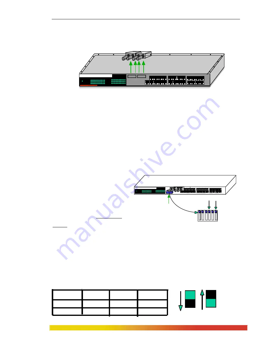
Step 3. Remove FKM Module
Gently pull the FKM module up and out of the connector socket (see Figure 3.4.3b).
Figure 3.4.3b: Removing an FKM Module
If the slot from which the FKM module has been removed is to remain unused,
be sure to install an FKM-BLNK face plate to cover it. If another FKM module is
replacing the one that has been removed, follow the steps as described for installing a
FKM module, discussed in Section 3.4.1.
Step 4.
Once FKM modules have been removed, the chassis cover should be replaced.
To do this, reverse the procedure in Section 3.4.1.
3.5
Manual settings for Fiber ports (HDX or FDX)
The factory default settings on Magnum 4K24’s optional fiber ports
are at full-duplex (FDX). Each fiber
port can be set as half-duplex
(HDX) by manually settings the
DIP switches. These are provided
under the fiber ports inside of the
chassis as shown in the figure 3.5.
The blue DIP switches control half-
duplex and full-duplex of fiber port # 2 and # 4.
Fig 3.5 Dip Switch Settings
If a user toggles switch 4 to the
DOWN
position, then fiber port # 2 will be set to half-
duplex. The factory default settings for fiber ports will be always
UP
position for full-
duplex.
Magnum 4024C Switch
100M
Col/FDX
Link/Act
Power
100M
Col/FDX
Link/Act
2 4X 6 8 10 12 14 16 18 20 22 24
1X 1 3X 5 7 9 11 13 15 17 19 21 23
FKM
2X 4X 6 8 10 12 14 16 18 20 22 24
1 X 1 3 5 7 9 11 13 15 17 19 21 23
Magnum 4024F Switch
100M
Col/FDX
Link/Act
Power
100M
Col/FDX
Link/Act
TX X TX RX
DIP Switches
Port # 4
1 2 3 4 5 6
Port # 2
Front View
Full-duplex
DIPSwitch Settings for Fiber Half Duplex
SW
Port
Down
Factory Settings
UP
4
6
2
4
Half duplex
Half duplex
Full duplex
Full duplex
Half-duplex


