background image

• Setup Page Display?–– 

allows you to select the fields displayed in the data section of

the sounder page. The following options are available:

• 1 Field   

• 3 Fields & Compass

• 1 Field & Compass

• 3 Fields & CDI

• 1 Field & CDI

• 5 Fields

• 3 Fields

To change the page display:

1. Highlight the ‘Setup Page Display?’ option and press 

T

.

2. Highlight the desired field and press 

T

.

3. Select a page display option and press 

T

.

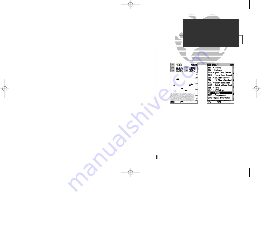
• Change Data Fields?—

allows you to specify the data displayed in each data field

used on the sounder page. The following options are available:

• BRG- bearing to active waypoint

• DIS- distance to active waypoint

• SOG- speed over ground

• COG- course over ground

• ETE- estimated time enroute

• ETA- estimated time of arrival

• XTK- crosstrack error

• VMG- velocity made good

• TRN- turn angle to waypoint

• VDC- DC voltage

• DPT- depth

• TMP- temperature (transducer option)

• STW- speed through water (transducer option)

To change a data field:

1. Highlight the ‘Change Data Fields?’ option and press 

T

.

2. Move the field highlight to the desired field and press 

T

.

3. Select a data field option and press 

T

.

4. When finished press 

Q

.

• 

Restore Defaults?—

resets all sounder page options to the factory settings, except
the sounder setup page options. Restoring defaults on the
sounder setup page is addressed in the sounder setup page
options menu (See page 35).

A.

The sounder page can be configured to display up
to five data fields simultaneously.

B.

Any of thirteen information options may be
shown in a designated data field.

31

A

B

SECTION

3

SOUNDER PAGE

Sounder Options

GPS 135 Rev C  8/4/98 4:18 PM  Page 31

Содержание Sounder GPSMAP 135

Страница 1: ...GPSMAP 135 Sounder TM OWNER S MANUAL AND REFERENCE ZOOM ZOOM ZOOM OPTION MENU EDIT ENTER GPS 135 Rev C 8 4 98 4 16 PM Page 1...

Страница 2: ...dustrial Estate Romsey UK SO51 9AQ Tel 011 44 1794 519944 Fax 011 44 1794 519222 All rights reserved No part of this manual may be reproduced or transmitted in any form or by any means electronic or m...

Страница 3: ...a navigational aid or depth sounder to prevent collision grounding boat damage or personal injury The digital depth displayed is the depth under the back of your boat and not the front By the time a...

Страница 4: ...se harmful interference to radio communications There is no guarantee that interference will not occur in a particular installation If this equipment does cause harmful interfer ence the user is encou...

Страница 5: ...ogen sealed case for use in exposed locations Advanced Navigating and Plotting 250 alphanumeric waypoints with selectable icons and comments Built in worldwide database usable from 4096 to 64 nm scale...

Страница 6: ...herein are exclusive and in lieu of all other warranties expressed or implied including any liability arising under warranty of merchantability or fitness for a particular purpose statutory or otherw...

Страница 7: ...ur so that you may become more familiar with the unit This section will provide you with a basic working knowledge necessary to use the unit to its fullest potential Part Two is divided into sections...

Страница 8: ...ard Package GPSMAP 135 Sounder Unit External Antenna and 30 cable Power Data Cable Mounting Bracket Owner s Manual Quick Reference Card For assembly part number 010 00092 01 a standard transom mount t...

Страница 9: ...ain Menu Page 48 Viewing the main menu page and selecting submenus Section 7 Waypoints 49 57 Creating using and editing waypoints Section 8 GOTO MOB TracBack Functions 58 61 Going to a destination and...

Страница 10: ...graphically from the map Displays context sensitive options window Press MENU twice to display main menu page Activates highlighted fields and confirms menu options and data entry Turns the unit on a...

Страница 11: ...stalled on your vessel according to the instructions in Appendix A To turn the GPSMAP 135 Sounder on 1 Press and hold the P key until the power tone sounds The welcome page will appear while the unit...

Страница 12: ...rrent status of functions such as satellite signal reception activated alarms and also constantly shows the digital depth A signal strength bar for each satellite in view will appear on the lower half...

Страница 13: ...key to acknowledge the mariner s warning The satellite status page will appear as the receiver begins acquiring satellites From the status page you may also adjust the screen contrast and backlighting...

Страница 14: ...mulator warning Once the simulator has been started the status field at the top of the page will display a Simulating Navigation status Now you re ready to continue the rest of the tour Keep in mind t...

Страница 15: ...s below the compass tape show your current course and speed over ground along with a resettable trip odometer and depth display Your current latitude and longi tude along with a 12 24 hour clock appea...

Страница 16: ...nt symbol page 7 Use the R keypad to highlight the ANCHOR symbol 8 Press T to confirm the symbol 9 Press T again to confirm the DONE prompt and save the waypoint The waypoint is now stored in memory N...

Страница 17: ...ofter bottom while a thick whiteline shows a harder bottom A black line is used to show the point where water meets the whiteline This black line will follow the bottom contour along with any signifi...

Страница 18: ...layed in the function field at the top right corner of the page 2 Press T The underwater waypoint feature marks a waypoint s position and its depth This makes it easier to find and use an object such...

Страница 19: ...display Note the zoom function can only be deactivated by pressing the Z key up until the orig inal scale picture appears Pressing Q will not turn off the zoom function The zoom function operates in e...

Страница 20: ...earing to a posi tion and perform various waypoint and route functions The data window located at the top of the page provides a user selectable dis play of various navigation data including course sp...

Страница 21: ...the Q key to remove the cursor and recenter your boat on the map display As you become more familiar with the cursor you ll see that the map display actively scrolls or pans letting you explore areas...

Страница 22: ...the second method which will automatically place our vessel at the first route waypoint This will also give us an idea of how the O key is used throughout the GPSMAP 135 Sounder system to provide cont...

Страница 23: ...ly presentation of the surrounding shoreline Because the usable range of the built in database is only valid to 64 nm scale we no longer have full cartog raphy available Keep in mind that whenever you...

Страница 24: ...W 076 26 106 Use the data window to verify the cursor position 2 Press the T key to capture the cursor position 3 Use the R key to highlight the waypoint symbol field 4 Press T to access the symbol p...

Страница 25: ...aypoint relative to the direction you re moving The line down the center of the highway represents your desired track while the bottom of the page provides a graphic indication of your crosstrack erro...

Страница 26: ...also be configured to display any of eight different navigation information categories Let s change the ETE field to ETA esti mated time of arrival To change a data field 1 Press the O key to display...

Страница 27: ...onfirm To reset the boat speed to zero 1 Press the O key 2 Highlight the Setup Simulator option 3 Press T 4 Press T to access the SOG field 5 Press the LEFT arrow of the R keypad to clear the speed en...

Страница 28: ...e track log and start a TracBack route To delete the track log 1 Highlight the Delete Track option and press T A confirmation page will appear 2 Highlight the Yes prompt and press T to confirm 3 Press...

Страница 29: ...s of the GPSMAP 135 Sounder in detail If you are unable to locate a specific option or function please refer to the index on pages 96 98 Thank you for choosing the GARMIN GPSMAP 135 Sounder navigation...

Страница 30: ...r will not be highlighted The sky view shows a bird s eye view of the position of each satellite relative to the receiver s last known position The outer circle represents the horizon track up the inn...

Страница 31: ...eometry have been acquired and a 2 dimensional position fix latitude and longitude is being calculated 2D Differential Navigation will appear when you are receiving DGPS corrections in 2D mode 3D Navi...

Страница 32: ...llows you to select between a north up or track up sky view display Setup Simulator allows you to define speed course and position values while in simulator mode See the Getting Started Tour for more...

Страница 33: ...of the page indicates posi tion fix status and is described in detail on page 21 The units of measure for speed distance position and altitude are all user selectable through the navigation setup opt...

Страница 34: ...TMP temperature To change a data field 1 Highlight the Change Data Fields option and press T 2 Move the field highlight to the field you want to change and press T 3 Select the desired data field opti...

Страница 35: ...oft bottom while a thick whiteline shows a harder bottom A black line is used to show the point were the water meets the whiteline This black line will follow the contour of the bottom and show any ob...

Страница 36: ...confirm the selected range or Q to return to Auto mode To adjust manual range or switch from manual to auto mode 1 Press R keypad up or down until the desired depth range is displayed 2 Press T to con...

Страница 37: ...educed pictures with one showing the original scale and one at 1 4 the original depth scale 4X Full Screen Displays only the 4X zoomed picture on the full GPSMAP 135 Sounder screen Once activated the...

Страница 38: ...turns you to the standard sounder screen To mark an underwater waypoint 1 Press T to pause the moving screen display 2 Press the R keypad in any direction to activate the on screen cursor A data field...

Страница 39: ...e O key to display the map page options menu 2 Highlight the Setup Page Display option and press T 3 Select either of the entries for Fields Sounder and press T The split screen map sounder page funct...

Страница 40: ...f the screen will be highlight ed Use the R keypad to select the desired value and press T Set Range Mode allows you to select from auto manual or window modes To set the range mode 1 Highlight the Se...

Страница 41: ...estimated time of arrival XTK crosstrack error VMG velocity made good TRN turn angle to waypoint VDC DC voltage DPT depth TMP temperature transducer option STW speed through water transducer option To...

Страница 42: ...arches and displays other echo information thermoclines thin stumps etc as shades of gray Fish Only shows fish icons To select fish ID 1 Highlight the Fish ID option and press T The fish id submenu w...

Страница 43: ...e rejection off The OFF setting pre vents the unit from removing any perceived noise from the display The ON setting removes anything the unit thinks is cross talk noise and attempts to repair the dam...

Страница 44: ...to begin the calibration press T 5 Slowly accelerate your boat to a maximum safe cruising speed and then back down to a stop and press T The minimum and maximum speed which the unit is now calibrated...

Страница 45: ...cessed from the sounder setup options menu Manual or Auto Calibration whichever one currently is not selected and Restore Defaults Access the options menu by pressing O select an option and press T Se...

Страница 46: ...tination waypoint Whenever the cursor is active an additional data window will appear below to indicate the position range and bearing to the cursor or a selected waypoint or navaid Each data field ma...

Страница 47: ...empts to go off the display the zoom level may need to be adjusted to keep cartography on screen Whenever the R keypad is pressed the GPSMAP 135 Sounder will enter cur sor mode In cursor mode The curs...

Страница 48: ...ion directly from the map display To select an on screen waypoint or navaid with the cursor 1 Use the R keypad to move the cursor to the desired waypoint or navaid if there are several waypoints group...

Страница 49: ...d a G chart cartridge cartography will be displayed using the data with the best reso lution When the selected zoom range exceeds the resolution of the chart in use by up to two settings overzoom cart...

Страница 50: ...The default setting is on Measure BRG DIS allows you to measure the bearing and distance between any two points on the map display To measure the BRG DIS between two points 1 Highlight the Measure BR...

Страница 51: ...he R keypad to select the desired map item and press T A popup window will appear with the current settings displayed 2 Use the R keypad to highlight the scale you want to change 3 Press T to change t...

Страница 52: ...ta window 3 Press T to confirm the calibration offset The next option available from the map configuration page is the set map colors option which allows you to define the fill color grayscale of the...

Страница 53: ...cessed in this mode To modify or access the sounder page display press Qor J until the actual sounder page appears make any desired changes and then return to the split screen map page 2 Fields 2 Fiel...

Страница 54: ...t name DPT depth TMP temperature STW speed through water To change a data field 1 Highlight the Change Data Fields option and press T 2 Move the field highlight to the desired field and press T 3 Sele...

Страница 55: ...good VMG to your destination The middle section of the screen provides visual guidance to the waypoint on a graphic highway display The line down the center of the highway represents your desired tra...

Страница 56: ...s are available from 1 4 to 4 nm with a default setting of 1 4 nm To change the highway perspective scale 1 Press the up or down arrow of the Z key to select the desired setting Navigation Page Option...

Страница 57: ...isplayed No Waypoints no waypoints will be displayed To configure the highway display 1 Highlight the Configure Highway option and press T 2 Select the desired option and press T Restore Defaults rese...

Страница 58: ...twice The 11 submenus are divided into categories by function To select a submenu from the main menu page 1 Highlight the submenu you want to view and press T For specific instructions on using a subm...

Страница 59: ...to mark your present position To mark your present position 1 Press the M key The mark position page will appear with a default three digit name for the new waypoint 2 To accept the waypoint with the...

Страница 60: ...e Map Posn or the Use NAVAID Posn option and press T 4 To accept the waypoint with the default name symbol and comment the depth at that position press T 5 To enter a different name symbol or comment...

Страница 61: ...created by manually entering a position s coordinates or referencing a stored waypoint through the Create Waypoint submenu option on the main menu page To create a new waypoint by manually entering it...

Страница 62: ...s O to select the waypoint from the nearest list waypoint list or map display Leave the reference field blank to use your present position 5 Press T to begin entry of the bearing from your reference w...

Страница 63: ...selected waypoint To change the waypoint symbol 1 Highlight the waypoint symbol field and press T 2 Use the R keypad to select the desired symbol and press T to confirm To change the position coordin...

Страница 64: ...ursor arrow 4 Use the R keypad to move the cursor arrow to the desired position The cursor s coor dinates along with the distance and bearing from the waypoint s position will be dis played at the top...

Страница 65: ...nts of safety in emergency situations To scroll through and review the nearest waypoint list 1 Highlight the Nearest Waypoints option and press T 2 Use the R keypad to scroll through the list in eithe...

Страница 66: ...isplay 4 Press T to confirm The distance field will now be highlighted 5 Press T to begin entry of the proximity radius 6 Use the R keypad to enter a distance value to 99 99 units and press T To turn...

Страница 67: ...s option from the main menu page and press T 2 Use the R keypad to scroll through the list in the desired direction 3 Press T to review the highlighted waypoint 4 Press T to return to the list To dele...

Страница 68: ...MAP at the navaid or map position To activate a GOTO from the map display 1 Press the G key twice 2 To select an existing user waypoint highlight the waypoint on screen and press T 3 To select a navai...

Страница 69: ...om a list of the nine nearest waypoints to your present position To select a nearest waypoint as a GOTO destination 1 Highlight the Show Nearest Waypoints option and press T 2 Select the desired waypo...

Страница 70: ...ce your path using the track log automatically stored in the receiver s memory which will eliminate the need to store waypoints along the way TracBack routes are created by reducing your track log int...

Страница 71: ...sest to the destination If the track log interval is set to the Time option the route may not follow your exact path keep the interval set to resolution for best performance If the receiver is turned...

Страница 72: ...t or navaid to the route use the arrow pointer to highlight the desired waypoint on screen and press T 6 To add a new waypoint to the route use the arrow pointer to select the desired map position and...

Страница 73: ...T To remove a route waypoint 1 Highlight the Remove option and press T To move a route waypoint 1 Highlight the Move option and press T 2 Move the cursor to the new map position and press T To insert...

Страница 74: ...e route edit options 1 Press O To select a menu option 1 Highlight the desired option and press T The following options are available Edit As Text allows you to modify a route by text entry To edit a...

Страница 75: ...d pressing T Activate Route activates the route you are editing and begins navigation Invert Route activates the route you are editing in reverse order and begins navi gation Center On Vessel redraws...

Страница 76: ...rom the route options page To display the route options 1 Press O To select a menu option 1 Highlight the desired option and press T The following options are available from the route list page Create...

Страница 77: ...To copy a route 1 Highlight the Copy Route option and press T The selected route will appear as the copy from route and the first open storage route will appear as the copy to route 2 Press T to conf...

Страница 78: ...e to waypoint first From the active route page you can Change the route comment see page 66 for instructions Edit the route as text see pages 64 65 for instructions Additional functions for the active...

Страница 79: ...efine the data displayed in the distance and ETE fields four data options are available DIS distance to active wpt DTK desired track ETE estimated time enroute ETA estimated time of arrival Restore De...

Страница 80: ...val Resolution records track plot based upon a user defined variance from your course over ground The resolution option is the default setting and is recommended for the most efficient use of memory a...

Страница 81: ...the second waypoint field and follow the steps above to select the destination waypoint 5 Enter a speed for your trip in the speed field or press O to select your current SOG for the speed value 6 Ent...

Страница 82: ...the cumulative values for the entire route The route planning mode will also let you plan cumulative totals for multiple route legs by using the Hold First Waypoint selection from the options window T...

Страница 83: ...face settings of the GPSMAP 135 Sounder The system setup submenu is used to select the operating mode date and time formats tone preferences backlight timeout and display contrast Operational Mode let...

Страница 84: ...nts Display Contrast provides a slide bar to adjust the LCD screen contrast in order to compensate for changes in temperature or lighting conditions Backlight Timeout provides an automatic shutoff for...

Страница 85: ...or speed and distance measurements You may select from nautical statute or metric formats The default setting is nautical Depth Units selects the format for depth contour display on G chart offshore c...

Страница 86: ...ounder s response time to changes in track or ground speed Three settings are available automatic on or off The auto default setting will monitor the changes in your current track and speed and adjust...

Страница 87: ...ailable Off No arrival alarm will sound Auto An arrival alarm will sound one minute before the destination based upon your current speed and course over ground On An arrival alarm will sound at the al...

Страница 88: ...pendix A for additional NMEA sentence information No In No Out provides no interfacing capabilities RTCM In NMEA Out allows DGPS beacon receiver input and also provides selectable NMEA output RTCM In...

Страница 89: ...be 304 0 kHz with a bit rate of 100 bps or the last DGPS frequency bit rate selected To tune a DGPS frequency 1 Select the RTCM In NMEA Out format from the options page 2 Highlight the beacon receiver...

Страница 90: ...135 Sounder is on a confirmation tone will sound when the cartridge has been properly installed and accepted 4 Close the cover If you insert a G chart cartridge and get a card format not recognized me...

Страница 91: ...see page 40 Whenever you zoom past the usable range of the current electronic chart the range field will display Ovr Zm or No Map These warnings indicate that although you may still have cartography y...

Страница 92: ...dome antenna or mast Sailboat users should avoid mounting the antenna high on the mast to pre vent inaccurate speed readings caused by excessive heeling Most marine VHF and loran antennas will not ser...

Страница 93: ...rtridge The mounting surface should be heavy enough to support the unit and protect it from excessive vibration and shock For flush mounting make sure the flat panel is between 0 08 and 0 30 2 to 7 7m...

Страница 94: ...ghtly between the unit s flange and bracket lobe 5 Tighten knobs and connect the power data and antenna cables Transducer Installation For installation please refer to the booklet included with the tr...

Страница 95: ...MAP 135 Sounder two ferrite bead filter clamps are included for attachment to the unit s cables The clamps attach to your transducer and power cables near the point at which they connect to the back o...

Страница 96: ...ON B APPENDIX Wiring and Specifications PIN 1 red 10 40 volts DC PIN 2 black Ground PIN 3 blue NMEA out PIN 4 brown NMEA in PIN 5 white No connection PIN 6 green No connection PIN 7 yellow alarm low 1...

Страница 97: ...ontinuous Position Accuracy 1 5 meters 3 16 ft 15 meters 49 ft RMS Velocity Accuracy 0 1 knot RMS steady state 999 knots max Dynamics 6g s Sounder Power Output 300 WRMS 2400 W peak to peak Frequency 2...

Страница 98: ...es to verify the position indicated Max Calibration Is 5000mt 16 400 ft You have exceeded the maximum possible map calibration Memory Battery Power is Low The internal battery that stores waypoints ro...

Страница 99: ...s Full You have attempted to create more than 20 routes Route Waypoint was Deleted A route way point entered does not exist in the database and has been deleted from the route RTCM Input has Failed DG...

Страница 100: ...Austria Austria Bellevue IGN Efate and Erromango Islands Bermuda 1957 Bermuda 1957 Bermuda Islands Bogata Observ Bogata Obsrvatry Colombia Campo Inchspe Campo Inchauspe Argentina Canton Ast 66 Canton...

Страница 101: ...ston Island Johnston Island Kandawala Kandawala Sri Lanka Kandawala Sri Lanka Kerguelen Islnd Kerguelen Island Kertau 1948 West Malaysia Singapore L C 5 Astro Cayman Brac Island Liberia 1964 Liberia 1...

Страница 102: ...S Chile Puerto Rico Puerto Rico Virgin Isl Qatar National Qatar National Qatar Qornoq Qornoq South Greenland Reunion Reunion Mascarene Island Rome 1940 Rome 1940 Sardinia Isl RT 90 Sweden Santo Dos S...

Страница 103: ...of Arrival ETA The time of day of your arrival at a destination Estimated Time Enroute ETE The time remaining to your destination at your present speed Grid A coordinate system that projects the eart...

Страница 104: ...rse Mercator UTM A grid coordinate system that projects global sec tions onto a flat surface to measure position in specific zones Velocity Made Good VMG The speed you are traveling in the direction o...

Страница 105: ...to W157 5 11 W157 5 to W142 5 10 W142 5 to W127 5 9 W127 5 to W112 5 8 W112 5 to W097 5 7 W097 5 to W082 5 6 W082 5 to W067 5 5 W067 5 to W052 5 4 W052 5 to W037 5 3 W037 5 to W022 5 2 W022 5 to W007...

Страница 106: ...Cursor Movement 11 38 D Data Field Entry 13 Data Window 62 Date Time Formats 74 Datums 90 92 Definitions 93 94 Desired Track DTK 93 Depth Contours 75 Depth Units 75 Dilution of Precision DOP 21 DGPS...

Страница 107: ...81 Operation Setup 73 75 Overzoom Mode 39 P Packing List vi Page Sequence 5 Physical Specifications 87 Point to Point Planning 71 Position Format 75 Position Mode 37 Position Page 23 24 Velocity Filte...

Страница 108: ...ion 73 T Table of Contents vii Time Offsets 73 74 95 Timer Alarm Setup 77 Tone Selection 74 TracBack Function 60 61 Track Log 70 Track Memory 70 Track Plot Resolution 70 Track Recording 70 Trip Odomet...

Страница 109: ...ation 1200 E 151st Street Olathe KS 66062 USA GARMIN Europe LTD Unit 5 The Quadrangle Abbey Park Industrial Estate Romsey SO51 9AQ UK Part Number 190 00107 00 Rev C Printed in Taiwan GPS 135 Rev C 8 4...

Отзывы: