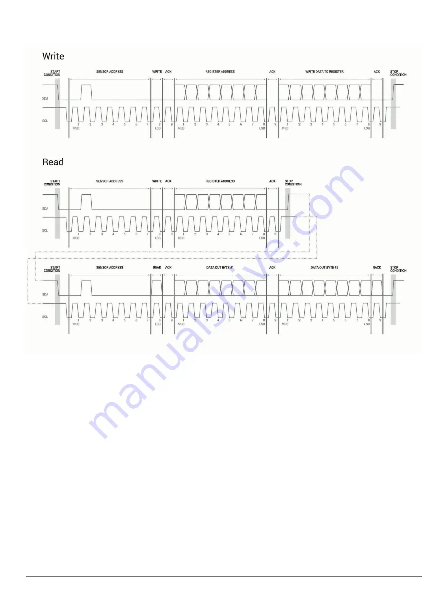
I2C Protocol Information
The sensor module has a 7-bit slave address with a default value of 0x62 in hexadecimal notation. The effective 8 bit I2C address is
0xC4 write, 0xC5 read. The device will not respond to a general call.
The last NACK in the read is optional, but the formal I2C protocol states that the master shall not acknowledge the last byte.
I2C Protocol Operation
This protocol description uses the term
master
to refer to the
host controller, and the term
LIDAR device
to refer to the
LIDAR-Lite v4 LED device acting as a slave on the I2C bus.
When working with the I2C serial bus protocol, the LIDAR
device operates as follows.
1
The master initiates data transfer by establishing a start
condition, which consists of a high-to-low transition on the
SDA line while SCL is high.
2
The master sends an address byte, which consists of the 7-
bit slave address.
3
The master sends a read/write bit with a zero state, which
indicates a write request. A write operation is used as the
initial stage of both read and write transfers.
4
If the slave address corresponds to the LIDAR device
address, the LIDAR device responds by pulling SDA low
during the ninth clock pulse. This operation is considered the
acknowledge bit. At this stage, all other devices on the bus
remain idle while the selected LIDAR device waits for data to
be written to or read from its shift register.
5
Data transmits over the serial bus in sequences of nine clock
pulses (eight data bits followed by an acknowledge bit).
These transmissions must occur on the SDA line during the
low period of SCL and remain stable during the high period of
SCL.
6
The master sends an 8-bit data byte following the slave
address, which loads the I2C control register on the LIDAR
device with the address of the first control register to be
accessed.
7
The master requests a read operation from the LIDAR device
or sends a write operation to the LIDAR device.
Read Operation
After the master establishes communication with the LIDAR
device, you can obtain a reading from the LIDAR device.
1
The first data frame sets the address of the desired read
register.
2
The master sends a stop bit at the completion of the first data
frame.
3
The master initiates a new start condition, which consists of
the slave I2C device address with the read bit set (one state).
4
The LIDAR device sends an acknowledge bit to the master
when it receives a valid address.
4


