190-01007-C1
GTN Xi Part 23 AML STC Maintenance Manual
Rev. 1
Page 6-19
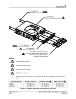
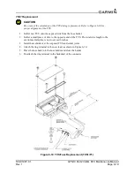
TVS1 Replacement
CAUTION
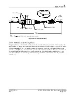
Be aware of the orientation of the TVS during replacement. Refer to Figure 6-10 for
proper alignment of the TVS.
1. Solder new TVS onto the exposed wire from the fuse holder.
2. Solder a small piece of wire to the opposite end of the TVS. The total wire length to the
environmental splice is not to exceed 6 inches.
3. Install heat shrink over the exposed TVS and solder joints.
4. Attach the ring terminal to the new lead, as shown in Figure 6-10.
5. Place the fuse back into the fuse holder and close the holder.
6. Re-attach the ring terminal to the backshell of the connector.
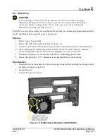
Figure 6-10 TVS/Fuse Replacement (TVS1/F1)
Содержание GTN Xi Series
Страница 42: ......
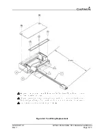
Страница 92: ...190 01007 C1 GTN Xi Part 23 AML STC Maintenance Manual Rev 1 Page 6 17 Figure 6 9 Fan Wiring Replacement...
Страница 163: ......


