


5
GSD 20 Sonar Module
I
NSTALLATION
I
NSTRUCTIONS
W
IR
E
C
O
LO
R
GARMIN GSD 20
SOUNDER MODULE
BL
AC
K
O
R
AN
G
E
R
ED
W
H
IT
E/
BL
U
E
BL
AC
K
R
ED
BL
U
E
YE
LL
O
W
W
H
IT
E/
BR
O
W
N
W
IR
E
C
O
LO
R
FU
SE
1.
5A
FU
SE 2A
TO
TRANSDUCER
ON
OFF
SEE NOTE 3 OPTION 1
ON
OFF
SEE NOTE 3 OPTION 2
BA
TT
ER
Y
10
-3
5
VO
LT
S
D
C
B
ASIC
W
IRING
FOR
THE
G
ARMIN
GSD 20
TO
A
S
INGLE
GPSMAP
276C/296/376C/396
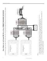
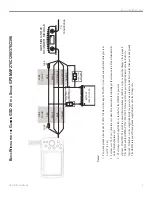
Notes:
1.
Power and ground wires require 18
AWG.
All other wires require 22
AWG. Use 4-conductor
, shielded wiring for runs
over 30’
(9.1 m).
2.
For runs over 30’
(9.1 m), the drain wire must be connected to the shielding of the extension run. Do not terminate the
end of the shield drain wire.
3.
The Orange wire must be pulled low (-) in order for the GSD 20 to power on.
Option 1: If the GSD 20 is wired to a circuit that is switched on the Red (+) wire, connect the Orange wire to ground. The GSD 20 and the GPSMAP
276C/296/376C/396 turn on/of
f when power is applied/removed to the Red wire.
Option 2: If the Red (+) wire is applied directly to a power source, install a switch between the Orange wire and ground. The GSD 20 turns on/of
f when ground is applied/removed to the Orange wire.


