background image

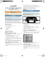
GSD 24 Transducer Adapter 

Installation Instructions

About the GSD 24 Transducer Adapter

 WARNING

See the 

Important Safety and Product Information

 guide in the GPS device 

product box for product warnings and other important information.

NOTICE

The GSD 24 adapter is not meant for use with a Garmin differential 8-pin 

transducer. Do not cut a Garmin differential 8-pin transducer; instead, plug it 

directly into the GSD 24 according to the 

GSD 24 Installation Instructions

.

Use this adapter to connect a non-differential transducer, such as a legacy 

Garmin/Airmar

®

 6-pin transducer, to a GSD

 24 sounder. In order to adapt 

a non-differential transducer for use with a Garmin differential sounder, you 

must cut the connector from your existing non-differential transducer and 

connect the wires to the wire block inside the GSD 24 Transducer Adapter by 

following these instructions.

Tools Needed

•  Drill and 

1

/

8

 in. (3.2 mm) drill bit

•  #2 Phillips screwdriver
•  3 mm flat screwdriver
•  Cable ties (optional)
•  Wire cutter
•  Wire stripper
• 

13

/

16

 in. (21 mm) wrench

Mounting the Adapter

Selecting a Mounting Location

Consider the following conditions when choosing a location to mount the 

GSD 24 Transducer Adapter.
•  The adapter cable should easily reach the transducer connector on the 

GSD 24 when mounted.
The adapter cable length is 24 in. (60.1 cm).

•  The adapter should not be installed in a location where it is submerged in 

water.

•  The adapter should be located at least 6 in. (15.25 cm) from electrical 

interference such as a motor.

•  If there is not a mounting surface suitable for using the included screws, 

the adapter can be secured to a structure using cable ties (not included).

Fastening the Adapter to the Mounting Location

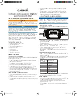
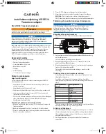
1.  Use the included template (page 19) to mark the pilot-hole locations.
2.  Drill the two pilot holes with a 

1

/

8

 in. (3.2 mm) drill bit.

3.  Install the included screws in the pilot holes, but do not tighten them flush 

with the surface.

4.  Place the GSD 24 adapter on the screws and slide it in place.
5.  Tighten the screws until the device is securely fastened to the surface.

NOTE:

 You may find it easier to connect the wires with the GSD 24 

adapter unmounted, and then complete the mounting process.

Connecting a Legacy Transducer to the Adapter

NOTICE

The GSD 24 adapter is not meant for use with a Garmin differential 8-pin 

transducer. Do not cut a Garmin differential 8-pin transducer; instead, plug it 

directly into the GSD 24 according to the 

GSD 24 Installation Instructions

.

Preparing the Legacy Transducer

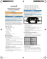
1.  Cut the connector from a non-differential transducer 

, as close to the 

connector as possible.

2.  Feed the cut end of the cable through the nut 

 on the side of the housing 

and pull it through the other side.
Do not tighten the nut at this time.

3.  Use the wire stripper to remove about 3 

1

/

2

 in. (90 mm) of the outer cable 

jacket 

➌ 

and foil shield. 

4.  Use the wire stripper to remove about 

1

/

4

 in. (6 mm) of the insulation from 

each internal wire 

.

  Tinning each of the stripped wires is recommended, but not necessary.

Connecting the Legacy Transducer Wires

Connect the wires to the wire block in the adapter using a 3 mm flat 

screwdriver. 
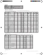
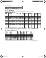
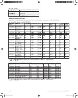
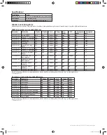
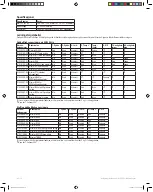
Consult the wiring table when connecting the wires. Specific examples of 

many Garmin/Airmar transducer wire colors are provided on page 2.

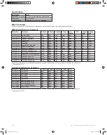
Wire Block 

Number

Wire Function

1

Depth +

2

Depth -

3

Shield

4

Ground

5

Temp*

6

XID

7

Speed power

8

Speed data

*If your transducer does not have temperature capability, you must install 

a jumper between connectors 4 and 5 on the wire block.

Finalizing the Connection

1.  After all the wire connections are secure, use a 

13

/

16

 in. (21 mm) wrench to 

tighten the nut around the transducer cable.
When tightened correctly you will not be able to pull the transducer cable 

out of the housing.

2.  Place the lid on the adapter and secure it with the four captive Phillips 

screws.

190-00789-08_0C.indb   1

11/8/2011   7:58:48 AM

Содержание GSD 24

Страница 1: ...all the included screws in the pilot holes but do not tighten them flush with the surface 4 Place the GSD 24 adapter on the screws and slide it in place 5 Tighten the screws until the device is secure...

Страница 2: ...00 Airmar M260 for 500W sonar units Blue Black Bare NA NA Orange NA NA 010 10451 00 Airmar B260 for 500W sonar units Blue Black Bare White Brown NA NA NA 010 10982 00 Airmar B60 with 20 tilt Blue Bla...

Страница 3: ...mm 1 8 po 3 Installez les vis fournies dans les trous d implantation mais ne les encastrez pas compl tement 4 Placez l adaptateur GSD 24 sur les vis et faites le glisser son emplacement 5 Serrez les v...

Страница 4: ...Noir D nud N A N A N A N A N A 010 10445 00 Airmar M260 pour sondeurs 500 W Bleu Noir D nud N A N A Orange N A N A 010 10451 00 Airmar B260 pour sondeurs 500 W Bleu Noir D nud Blanc Marron N A N A N A...

Страница 5: ...riferimento con una punta da trapano da 3 2 mm 1 8 poll 3 Installare le viti in dotazioni nei fori di riferimento ma non serrarle a filo della superficie 4 Collocare l adattatore GSD 24 sulle viti e...

Страница 6: ...W Blu Nero Senza rivestimento ND ND Arancione ND ND 010 10451 00 Airmar B260 per unit sonar da 500 W Blu Nero Senza rivestimento Bianco Marrone ND ND ND 010 10982 00 Airmar B60 con inclinazione di 20...

Страница 7: ...ch nicht so fest an dass sie b ndig mit der Oberfl che abschlie en 4 Setzen Sie den GSD 24 Adapter auf die Schrauben und positionieren Sie ihn ordnungsgem 5 Ziehen Sie die Schrauben an bis das Ger t s...

Страница 8: ...Echolote Blau Schwarz Blank n z n z Orange n z n z 010 10451 00 Airmar B260 f r 500 W Echolote Blau Schwarz Blank Wei Braun n z n z n z 010 10982 00 Airmar B60 mit Neigungswinkel von 20 Blau Schwarz B...

Страница 9: ...Coloca los tornillos incluidos en los orificios gu a pero no los aprietes de forma que los empotres en la superficie 4 Coloca el adaptador del GSD 24 en los tornillos y desl zalo hasta que encaje 5 Ap...

Страница 10: ...do N D N D N D N D N D 010 10445 00 M260 Airmar para unidades de sonda de 500 W Azul Negro Desnudo N D N D Naranja N D N D 010 10451 00 B260 Airmar para unidades de sonda de 500 W Azul Negro Desnudo B...

Страница 11: ...to com uma broca de 3 2 mm 1 8 pol 3 Coloque os parafusos inclu dos nos orif cios do piloto mas n o os aperte rente superf cie 4 Coloque o adaptador GSD 24 nos parafusos e desloque o para a posi o ade...

Страница 12: ...0 Airmar M260 para unidades de sonda de 500 W Azul Preto Sem isolamento NA NA Laranja NA NA 010 10451 00 Airmar B260 para unidades de sonda de 500 W Azul Preto Sem isolamento Branco Castanho NA NA NA...

Страница 13: ...e skruer i forboringshullerne men skru dem ikke helt ned i niveau med overfladen 4 Placer GSD 24 adapteren p skruerne og skub den p plads 5 Stram skruerne s enheden sidder forsvarligt fastgjort til ov...

Страница 14: ...NA NA 010 10445 00 Airmar M260 til 500 W ekkolodsenhed Bl Sort Uisoleret NA NA Orange NA NA 010 10451 00 Airmar B260 til 500 W ekkolodsenhed Bl Sort Uisoleret Hvid Brun NA NA NA 010 10982 00 Airmar B6...

Страница 15: ...8 tommer 3 Sett de medf lgende skruene inn i styrehullene men ikke stram dem til slik at de g r i ett med overflaten 4 Plasser GSD 24 adapteren p skruene og skyv den p plass 5 Stram til skruene til en...

Страница 16: ...I T I T I T I T 010 10445 00 Airmar M260 for 500W ekkoloddenheter Bl Svart Uisolert I T I T Oransje I T I T 010 10451 00 Airmar B260 for 500W ekkoloddenheter Bl Svart Uisolert Hvit Brun I T I T I T 01...

Страница 17: ...h len med en 3 2 mm 1 8 tums borrspets 3 S tt i de medf ljande skruvarna i rikth len men skruva inte t dem helt 4 Placera GSD 24 adaptern p skruvarna och skjut in den p plats 5 Skruva t skruvarna till...

Страница 18: ...445 00 Airmar M260 f r 500 W ekolodsenhet Bl Svart Blottad Orange 010 10451 00 Airmar B260 f r 500 W ekolodsenhet Bl Svart Blottad Vit Brun 010 10982 00 Airmar B60 med 20 lutning Bl Svart Blottad Vit...

Страница 19: ...ation Instructions 19 Mounting Template Mod le de montage Modello per il montaggio Montageschablone Plantilla de montaje Modelo de montagem Monteringsskabelon Monteringsmal Monteringsmall 190 00789 08...

Страница 20: ...ight laws this manual may not be copied in whole or in part without the written consent of Garmin Garmin reserves the right to change or improve its products and to make changes in the content of this...

Отзывы: