


190-00303-A3
GSB 15 Installation Manual
Rev. 3
Page 2-1
2 INSTALLATION OVERVIEW
2.1 Introduction
This section provides the equipment information for installing the GSB 15 and related optional
accessories. Installation of the GSB 15 must follow the data detailed in this manual. Cabling is typically
fabricated by the installing agency to fit each particular aircraft. Always follow acceptable avionics
installation practices per advisory circulars AC 43.13-1B and AC 43.13-2B or later FAA approved
revisions.
2.2 Installation Materials Required but not Supplied
• All wiring required for installation
• Circuit breaker
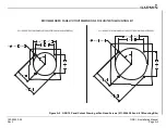
2.3 Installation Configurations
The GSB 15 can be installed in either a rear connector or side connector configuration. Refer to the outline
and installation drawings in
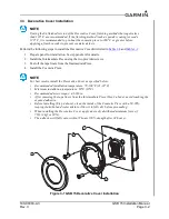
Optional 2.25” and 3.125” mounting kits are also available (see
) to mount the GSB 15 in
existing instrument panel holes.
NOTE
At least 2 of the 4 provided mounting holes must be used (diagonally from each other) to
mount the GSB 15.
2.4 Special Tools Required
A crimp tool is required for the GSB 15 installation. Recommended and optional crimp tools are as
follows:
Recommended Crimp tool:
•
Molex Hand Crimp Tool, P/N 638190000
Optional:
Molex Insertion Tool for Micro-Fit 3.0 and CRC Male and Female Crimp Terminals, 20-30 AWG,
•