


Stainless-steel screws may bind when screwed into fiberglass
and overtightened. Garmin recommends applying an anti-seize
lubricant to the screws before installing them.
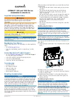
The included template and hardware can be used to mount the
device in your dashboard.
1
Trim the template and make sure it fits in the location where
you want to mount the device.
2
Remove the protective liner from the back of the template
and adhere it to the location where you want to mount the
device.
3
Using a 9.5 mm (
3
/
8
in.) drill bit, drill one or more of the holes
inside the corners of the solid line on the template to prepare
the mounting surface for cutting.
4
Using a jigsaw or rotary tool, cut the mounting surface along
the inside of the solid line indicated on the template.
5
Place the device in the cutout to test the fit.
6
If necessary, use a file and sandpaper to refine the size of
the cutout.
7
After the device fits correctly in the cutout, ensure the
mounting holes on the device line up with the pilot holes on
the template.
8
If the mounting holes on the device do not line up, mark the
new pilot-hole locations.
9
Using a 3.2 mm (
1
/
8
in.) drill bit, drill the pilot holes.
10
Remove the template from the mounting surface.
11
If you will not have access to the back of the device after you
mount it, connect all necessary cables to the device before
placing it into the cutout.
12
If necessary, cover unused connectors with the attached
weather caps to prevent corrosion of the metal contacts.
13
Install the foam gasket
À
on the back of the device.
The pieces of the rubber gasket have adhesive on the back.
Make sure you remove the protective liner before installing
them on the device.
14
Place the device in the cutout.
15
Secure the device to the mounting surface using the included
screws
Á
.
16
Install the decorative bezel by snapping it in place around the
edges of the device.
Connection Considerations
When connecting this device to power and to other Garmin
devices, you should observe these considerations.
• The power and ground connections to the battery must be
checked to make sure they are secured and cannot become
loose.
• For easier routing, the cables are packaged without the
locking rings installed. The cables should be routed before
the locking rings are installed.
• After installing a locking ring on a cable, you should make
sure the ring is securely connected and the o-ring is in place
so the power or data connection remains secure.
About the Wiring Harness
• The wiring harness connects the device to power, NMEA
®
0183 devices, and a lamp or a horn for visible or audible
alerts.
• The wiring harness is packaged without the locking ring
installed. You should route the cable before you install the
locking ring.
• After connecting a locking ring to the wiring harness, you
should make sure the ring is securely connected and the o-
ring is in place so the connection remains secure.
• The device has two internal NMEA 0183 ports that are used
to connect to NMEA 0183 compliant devices. When
connecting to a device for both transmitting and receiving,
you must make sure to use wires from the same internal
NMEA 0183 port.
• If it is necessary to extend the power and ground wires, you
must use 16 AWG (1.31 mm²) wire.
• If it is necessary to extend the NMEA 0183 or alarm wires,
you must use 22 AWG (.33 mm²) wire.
Item
Wire Color
Wire Function
À
Red
Power
Á
Black
Ground (power and NMEA 0183)
Â
Blue
NMEA 0183 internal port 1 Tx (out)
Ã
Brown
NMEA 0183 internal port 1 Rx (in)
Ä
Gray
NMEA 0183 internal port 2 Tx (out)
Å
Violet
NMEA 0183 internal port 2 Rx (in)
Æ
Orange
Accessory on
Ç
Yellow
Alarm low
Connecting the Wiring Harness to Power
WARNING
When connecting the power cable, do not remove the in-line
fuse holder. To prevent the possibility of injury or product
damage caused by fire or overheating, the appropriate fuse
must be in place as indicated in the product specifications. In
addition, connecting the power cable without the appropriate
fuse in place will void the product warranty.
If it is necessary to extend the power and ground wires, you
must use 18 AWG (0.82 mm²) wire.
1
Route the wiring harness to the power source and to the
device.
2
Connect the red wire to the positive (+) battery terminal, and
connect the black wire to the negative (-) battery terminal.
3
Install the locking ring and o-ring on the end of the wiring
harness.
4
Connect the wiring harness to the device by turning the
locking ring clockwise.
NMEA 0183 Connection Considerations
• The installation instructions provided with your NMEA 0183
compatible device should contain the information you need
to identify the transmitting (Tx) and receiving (Rx) A (+) and
B (-) wires.
2