


18
GPSMAP 4000/5000 Series Installation Instructions
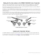
Wiring to an optional Alarm
The GPSMAP 4000/5000 series chartplotter can be used with a lamp, a horn, or both, to sound or flash an alert when the chartplotter displays a
message. The alarm does not need to be wired for the GPSMAP 4000/5000 chartplotter to function. The alarm circuit switches to a low-voltage
state when the alarm sounds. The maximum current is 100 mA, and a relay is needed to limit the current from the chartplotter to 100 mA. To
select between visual and audible alerts, install a switch.
Wiring to a lamp, a horn, or both.
+
-
Garmin
GPSMAP 4000/5000 series
chartplotter
WIrE
CoLor
rED (PoWEr)
BLACk (GnD)
YELLoW (ALArM)
BAttErY
10–35 Vdc
rELAY
100 mA MAX
CoIL CurrEnt
Horn
LAMP
FuSE
7.5 A - 42 V
PoWEr
CABLE
nMEA 0183
CABLE
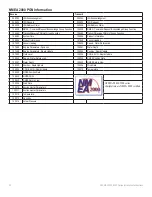
Wiring to a DB-9 PC Serial Connector
The GPSMAP 4008/4208/4010/4210/4012/4212/5008/5208/5012/5212 chartplotters can be connected to a PC with a serial port by wiring the
chartplotter to a DB-9 serial connector.
Wiring to a DB-9 Serial PC Connector
+
-
>
>
>
>
>
>
1
4
6
7
8
9
2
3
5
Garmin
GPSMAP 4000/5000 series
chartplotter
DB-9 Serial
PC Connector
BAttErY
10–35 Vdc
WIrE
SEE tABLE For
WIrE CoLorS
DB-9 PIn
nuMBErS
rED (PoWEr)
BLACk (PWr GnD)
FuSE
7.5 A - 42 V
BLACk (DAtA GnD)
rX / B(-)
rX / A(+)
PIn 5: GnD
PIn 3: tX
PoWEr
CABLE
nMEA 0183
CABLE
unConnECtED
PIn 2: rX
tX / B(-)
tX / A(+)
End View


