Garmin GPS 175 Скачать руководство пользователя страница 84

190-02207-A2

GPS 175/GNX 375/GNC 355 Part 23 AML STC Maintenance Manual

Rev. 3

Page 8-2

8.1 Overview

This section contains instructions for configuring the GPS 175/GNX 375/GNC 355, as well as checks to 

ensure the system is properly installed and functioning correctly. The steps that are not applicable to a 

particular installation may be skipped.

8.2 System Checkout

Original GPS 175/GNX 375/GNC 355 is Re-installed

If the removed GPS 175/GNX 375/GNC 355 is installed in its original position, no software loading or 

configuration setting changes are required. This does not include units that were returned for repair, as 

their software and configuration files are deleted during the repair testing process.
If the original GPS 175/GNX 375/GNC 355 is re-installed, configuration and software loading are not 

required. Refer to Section 6 of 

GPS 175 Part 23 AML STC Installation Manual

 (P/N 190-02207-A1), 

GNX 375 Part 23 AML STC Installation Manual

 (P/N 190-02207-A4), or 

GNC 355 Part 23 AML STC 

Installation Manual

 (P/N 190-02207-A5) (as applicable) for installation checkout procedures. 

New, Repaired, or Exchanged GPS 175/GNX 375/GNC 355 is Installed

If a new, repaired, or exchanged GPS 175/GNX 375/GNC 355 is installed, the AML approved software 

and the configuration files from the Configuration Log in the aircraft permanent records must be loaded to 

the unit. After this is accomplished, refer to Section 6 of 

GPS 175 Part 23 AML STC Installation Manual


(P/N 190-02207-A1), 

GNX 375 Part 23 AML STC Installation Manual

 (P/N 190-02207-A4), or 

GNC 355 

Part 23 AML STC Installation Manual

 (P/N 190-02207-A5) (as applicable) for installation checkout 

procedures.

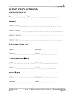
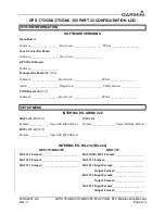
8.3 GPS 175/GNX 375/GNC 355 Configuration

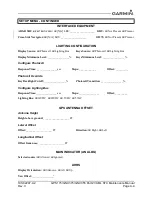
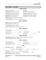
Retrieve the Configuration Log from the aircraft permanent records. For the maintenance activities that 

repaired or replaced the previous GPS 175/GNX 375/GNC 355, configure the unit as defined by the data 

contained in the Configuration Log.

NOTE

Ensure the Configuration Log remains with the aircraft permanent records upon 

completion of any maintenance activities.

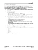
8.4 Regulatory Test (GNX 375)

The following regulatory tests are required to be performed per the 14 CFR sections referenced below. For 

the purpose of these tests, ensure the GNX 375 transponder is in Ground Test mode to simulate an airborne 

state. The Altitude Reporting Equipment Test is required to be performed for each altitude source 

interfaced to the transponder, including the GAE 12. These tests require the use of a Mode S transponder 

ramp tester, such as an Aeroflex IFR-6000 or TIC TR-220. For instructions on the operation of the ramp 

test equipment, refer to the manufacturer’s documentation.

1. Altitude Reporting Equipment Tests in accordance with 14 CFR Part 91.411 and Part 43 

Appendix E.

2. ATC Transponder Tests and Inspections in accordance with 14 CFR Part 91.413 and Part 43 

Appendix F.

Содержание GPS 175

Страница 1: ...C Maintenance Manual with Instructions for Continued Airworthiness for STC SA02636SE Aircraft make model registration number and serial number along with the applicable STC configuration information m...

Страница 2: ...l distribution of this manual or any revision hereto is strictly prohibited Garmin is a registered trademark of Garmin International or its subsidiaries GDU is a trademark of Garmin International or i...

Страница 3: ...ollowing license The free distribution and use of this software in both source and binary form is allowed with or without changes provided Distributions of this source code include the above copyright...

Страница 4: ...uring the term of this Agreement provided that the Licensed Software may only be used by Licensee on Devices on which the Licensed Software has been installed or otherwise made available by Garmin b R...

Страница 5: ...NOR ITS AFFILIATES MAKE ANY REPRESENTATION WARRANTY OR GUARANTEE STATUTORY OR OTHERWISE UNDER LAW OR FROM THE COURSE OF DEALING OR USAGE OF TRADE EXPRESS OR IMPLIED INCLUDING ANY WARRANTIES OF MERCHA...

Страница 6: ...l become and remain binding upon a Party only if such amendment or waiver is set forth in a writing by such Party No course of dealing between or among any persons having any interest in this Agreemen...

Страница 7: ...X 375 and GPS 175 GNC 355 3 4 3 1 2 Corrected descriptions of serial ports 3 4 3 1 3 Added Section 3 4 3 1 3 ADS B Source GPS 175 and GNC 355 Only 3 4 3 1 5 Added Section 3 4 3 1 5 GI 275 3 4 3 1 6 Ad...

Страница 8: ...o avoid damage to the units take precautions to prevent Electrostatic Discharge ESD when handling the unit connectors and associated wiring ESD damage can be prevented by touching an object of the sam...

Страница 9: ...5 4 5 Electrical Bonding Test 4 6 4 6 Overhaul Period 4 7 4 7 Additional Instructions 4 7 5 TROUBLESHOOTING 5 1 5 1 General Troubleshooting 5 2 5 2 Failure Annunciations 5 6 5 3 GPS 175 Connector Pino...

Страница 10: ...02207 A2 GPS 175 GNX 375 GNC 355 Part 23 AML STC Maintenance Manual Rev 3 Page ix 9 RETURN TO SERVICE PROCEDURE 9 1 9 1 Maintenance Records 9 1 APPENDIX A AIRCRAFT INSTALLATION SPECIFIC INFORMATION A...

Страница 11: ...75 GNC 355 Traffic Alert Troubleshooting 5 10 Figure 5 5 GNX 375 Traffic Alert Troubleshooting 5 11 Figure 5 6 XPDR Alert Troubleshooting 5 12 Figure 5 7 GNC 355 COM Alert Troubleshooting 5 17 Figure...

Страница 12: ...le 5 1 GPS 175 General Troubleshooting Guide 5 2 Table 5 2 GNX 375 General Troubleshooting Guide 5 3 Table 5 3 GNC 355 General Troubleshooting Guide 5 4 Table 5 4 J1751 Connector Pinout 5 24 Table 5 5...

Страница 13: ...ML STC Maintenance Manual Rev 3 Page 1 1 1 INTRODUCTION 1 1 Content Scope and Purpose 1 2 1 2 Organization 1 2 1 3 Applicability 1 3 1 4 Publications 1 3 1 5 Revision and Distribution 1 3 1 6 Referenc...

Страница 14: ...tion 3 Control and Operation Provides basic control and operation information specifically tailored to maintenance practices Section 4 Instructions for Continued Airworthiness Provides Instructions fo...

Страница 15: ...irplane Table 1 1 Reference Documentation 1 5 Revision and Distribution This document is required for maintaining the continued airworthiness of the aircraft Garmin Dealers may obtain the latest revis...

Страница 16: ...AML Approved Model List LPV Localizer Performance with Vertical Guidance Approach ARINC Aeronautical Radio Incorporated LRU Line Replaceable Unit ATC Air Traffic Control OAT Outside Air Temperature B...

Страница 17: ...5 GNX 375 GNC 355 Part 23 AML STC Maintenance Manual Rev 3 Page 2 1 2 SYSTEM DESCRIPTION 2 1 Equipment Descriptions 2 2 2 1 1 GPS 175 2 2 2 1 2 GNX 375 2 3 2 1 3 GNC 355 2 4 2 1 4 Flight Stream 510 2...

Страница 18: ...flight plan I O and GPS position interface with a PED Database Concierge only available through Flight Stream 510 The GPS 175 is capable of providing TSO C146e compliant GPS WAAS navigation for en ro...

Страница 19: ...on certified PED The built in Bluetooth will allow flight plan I O GPS position and ADS B Weather Traffic interface with a PED but will not allow software or database loading The GPS navigation functi...

Страница 20: ...display of attitude on a non certified PED The built in Bluetooth will allow flight plan I O GPS position and ADS B Weather Traffic interface with a PED but will not allow software or database loadin...

Страница 21: ...375 GNC 355 by replacing the front loaded data card to allow wireless database transfer with PEDs over WiFi Figure 2 4 Flight Stream 510 2 1 5 GAE 12 The GNX 375 allows for the use of an optional GAE...

Страница 22: ...3 4 5 Feature Enablement 3 10 3 4 6 SD Save 3 10 3 4 7 SD Load 3 11 Control and operation of the GPS 175 GNX 375 and GNC 355 occurs through the use of the touch display dual rotary knob and the Home...

Страница 23: ...ay be configured to be used by the display to automatically adjust the display backlighting with no further prompt Data Card Slot A card slot in the unit that accepts standard SD cards loader cards an...

Страница 24: ...to the pilot Photocell The photocell may be configured to be used by the display to automatically adjust the display backlighting with no further prompt Data Card Slot A card slot in the unit that ac...

Страница 25: ...ions to the pilot Photocell The photocell may be configured to be used by the display to automatically adjust the display backlighting with no further prompt Data Card Slot A card slot in the unit tha...

Страница 26: ...190 02207 A4 For detailed information on configuring the GNC 355 refer to GNC 355 Part 23 AML STC Installation Manual While in Configuration mode different pages can be selected by touching the desir...

Страница 27: ...nputs and outputs 3 4 3 1 2 RS 232 RS 422 The Interfaced Equipment RS 232 RS 422 page allows the configuration of data formats for serial ports Port 1 is capable of operating as an RS 232 port or an R...

Страница 28: ...B Logging GNX 375 Only External FPL Altitude Source Input GPS 175 and GNC 355 Only 3 4 3 4 Main Indicator Analog The Main Indicator Analog page allows the user to calibrate the OBS resolver and confi...

Страница 29: ...port is chosen for display by touching the ARINC 429 Port button to toggle between the input ports Select a port to display The GPS 175 GNX 375 GNC 355 will then display the label SSM Data and SDI for...

Страница 30: ...t alerts The XPDR page allows the user to view the status of all failure conditions active faults active warnings and associated pilot alerts For troubleshooting of these errors refer to the XPDR Aler...

Страница 31: ...and troubleshooting 3 4 4 16 XPDR Main Data GNX 375 Only The XPDR Main Data page provides the user access to the GPS Data Diagnostics and Air Data Diagnostics pages 3 4 4 17 Clear Config Settings To...

Страница 32: ...ion must match the unit saved to the card Before configuring determine if a previously saved configuration is available Use the following instructions to load the saved configuration information to a...

Страница 33: ...icing Information 4 3 4 2 1 Periodic Maintenance 4 3 4 2 2 Special Tools 4 3 4 3 Maintenance Intervals 4 4 4 4 Visual Inspection 4 5 4 5 Electrical Bonding Test 4 6 4 5 1 GPS 175 GNX 375 GNC 355 Bondi...

Страница 34: ......

Страница 35: ...test is executed automatically upon application of power to the units The built in tests BIT are continuously executed Detected errors are indicated as failure annunciations system messages or a comb...

Страница 36: ...Us On Condition Cleaning The GPS 175 GNX 375 and GNC 355 display and bezel may be cleaned periodically The front bezel and display should be cleaned with a soft cotton cloth dampened with clean water...

Страница 37: ...s properly oriented label facing left fully inserted and locked into position in the card slot on the front right side of the unit 2 Inspect for corrosion 3 Inspect switches knobs and buttons for dama...

Страница 38: ...ortion of aircraft metallic structure and ensure that the resistance is less than or equal to 2 5 m 4 Re install the backplate assembly and re install the GPS 175 GNX 375 GNC 355 in the mounting rack...

Страница 39: ...does not require overhaul at a specific time period Power on self test and BIT will monitor the health of the GPS 175 GNX 375 GNC 355 system If any LRU indicates an internal failure the unit may be r...

Страница 40: ...5 2 5 2 Failure Annunciations 5 6 5 3 GPS 175 Connector Pinout Information 5 23 5 3 1 J1751 62 Pin HD DSub 5 23 5 4 GNX 375 Connector Pinout Information 5 25 5 4 1 J3751 62 Pin HD DSub 5 25 5 4 2 J37...

Страница 41: ...ics are turned on Noise interference from other avionics Turn off all other avionics then turn on each piece of avionics one at a time to locate the source of the interference Route the GPS cable and...

Страница 42: ...ing OBS indication on GNX 375 does not agree with OBS setting OBS resolver input not calibrated or calibrated incorrectly Check wiring and calibration GNX 375 is not receiving heading from compass sys...

Страница 43: ...uting Check GPS antenna installation connections and cable routing The GPS antenna must be mounted on the top of the aircraft Antenna shaded from satellites Make sure the aircraft is clear of obstruct...

Страница 44: ...ed on the Discrete Inputs page found on the GNC Diagnostics page No transmit power to COM Make sure power input is connected to the COM 44 pin connector P3552 30 43 and 44 and ground to P3552 37 38 an...

Страница 45: ...Part 23 AML STC Maintenance Manual Rev 3 Page 5 6 5 2 Failure Annunciations If data fields become invalid the GPS 175 GNX 375 GNC 355 typically annunciates the failures with a large red X as shown in...

Страница 46: ...ors in the regristries of pilot stored data Reset config and reconfigure unit Cooling fan failure OR Cooling fan obstruction The inner knob push key is stuck in the enabled or pressed state Corrective...

Страница 47: ...n the enabled or pressed state Corrective Action Go to the Diagnostics Discrete Inputs page in Configuration Mode See Section 3 4 4 3 Press the key to cycle its operation If the state remains Active i...

Страница 48: ...n internal fault and transponder functionality may be unavailable The transponder is reporting an internal temperature above its upper operating limits The transponder is reporting an internal tempera...

Страница 49: ...al ADS B Out fault Check transponder is in correct mode Check that the transponder is in correct mode Corrective Action Cause Maintenance Log Message Communications with the GDL 88 GTX 345 has been lo...

Страница 50: ...ear view of the sky If faults still exist contact Garmin Corrective Action Corrective Action Inspect compatibility of transponder antenna and connections Traffic FIS B functions inoperative Cause ADS...

Страница 51: ...ftware Reset config and reconfigure unit Verify transponder antenna connections and coax installation Inspect wiring and connections Transponder Or 1090 ADS B Out Failure Cause Corrective Action High...

Страница 52: ...ction Transponder FPGA ROM Failure FPGA software load issue Reload software Transponder Or 1090 ADS B Out Failure Cause Corrective Action Transponder ROM Failure Software load issue Reload software Tr...

Страница 53: ...load or is invalid Service Soon Fault Cause Corrective Action ADS B In Electrical Fault ADS B In Calibration Fault Reload software Electrical fault with the ADS B board Possible internal hardware prob...

Страница 54: ...ction Corrective Action Audio ROM Fault Non volatile Memory Fault Audio database did not load or is invalid Non volatile data did not load or is invalid Service Soon Service Soon Fault Fault Cause Cau...

Страница 55: ...erify pressure sensor is functioning If using the GAE verify connections and then recalibrate Reload software System in ground test mode Power cycle the unit Warning Cause Corrective Action Alert Caus...

Страница 56: ...eased If faults still exist contact Garmin Corrective Action Corrective Action The COM remote transfer switch has been pressed for at least 2 seconds Corrective Action In Lockout mode the COM will tun...

Страница 57: ...ns are correct Cause A stored flight plan contains an airway that is no longer consistent with the current navigation database Corrective Action Touch the Show flight plan catalog actionable button an...

Страница 58: ...neous position Use other navigation source Cause Internal detection of erroneous GPS position data has occured Corrective Action Verify that the center conductor is not shorted to the braid in the coa...

Страница 59: ...ve Action If faults still exist contact Garmin Approach not active Approach guidance not available Cause The unit did not have the required HPL VPL to get into at least LNAV Corrective Action Low inte...

Страница 60: ...use the unit was unable to decode one or more waypoints The requested flight plan could not be imported because the user waypoint database is full Recheck file format and reload file if necessary Corr...

Страница 61: ...any source The WAAS diagnostic log failed to export to the SD card The ADS B log failed to export to the SD card A stored flight plan waypoint is no longer in the current navigation database Follow ac...

Страница 62: ...rete Input 2 Lighting Bus APPR 1 Power Input 1 Power Ground A T A RS 232 3 CDI RS 232 2 Discrete Out 4 I O I I 62 I B A Config Module 22 43 1 C C I T F O D D T R V OBS RS 232 1 B Demo Mode 3 TO FROM F...

Страница 63: ...RNET IN P IN 42 POWER INPUT 1 IN 12 VERTICAL UP OUT OUT 43 CONFIG MODULE V OUT 13 GND 44 OBS STATOR D 14 GND 45 OBS STATOR E GND 15 LATERAL LEFT OUT OUT 46 GND 16 TO FLAG 47 GND 17 LOI DISCRETE OUT 2...

Страница 64: ...I B2 A2 I R B D4 C2 O L 21 42 Ext Ident Input Air Ground Input Ext Standby Input Lighting Bus Ext Suppression Bus Switched Power Out Altitude Gray Code Input Power Input 1 Power Ground T A Ground RS 2...

Страница 65: ...C1 IN 43 PRESSURE SENSOR CONFIG MODULE V OUT 13 ALTITUDE GRAY CODE INPUT D4 IN 44 RESERVED 14 EXT STANDBY DISCRETE IN 6 IN 45 RESERVED 15 DISCRETE I O 1 I O 46 AUDIO OUT OUT 16 DISCRETE I O 2 47 AUDIO...

Страница 66: ...ESERVED 11 OBS ROTOR H GND OUT 33 DISCRETE OUT 4 OUT 12 OBS ROTOR C OUT 34 GND 13 APPROACH ANNUNCIATE OUT 35 GND 14 DISCRETE IN 2 IN 36 LATERAL GND 15 REMOTE GO AROUND 37 LATERAL FLAG OUT OUT 16 RESER...

Страница 67: ...COMPOSITE LIGHTING BUS APPR 1 VDI AIRCRAFT POWER AIRCRAFT GROUND T A GROUND RS 232 3 CDI OBS RS 232 2 I O I I 62 I B A CONFIG MODULE 22 43 1 C C I T F O D D T R V RS 232 1 B TO FROM FLAG R 1PPS I O AR...

Страница 68: ...IN 1A IN 42 AIRCRAFT POWER IN 12 VERTICAL UP OUT OUT 43 CONFIG MODULE POWER OUT 13 GND 44 OBS STATOR D IN 14 GND 45 OBS STATOR E GND 15 LATERAL LEFT OUT OUT 46 GND 16 TO OUT OUT 47 GND 17 LOI ANNUNCIA...

Страница 69: ...9 RESERVED 31 GND 10 RESERVED 32 RESERVED 11 COM MIC KEY IN 33 RESERVED 12 RESERVED 34 RESERVED 13 RESERVED 35 RESERVED 14 RESERVED 36 RESERVED 15 RESERVED 37 AIRCRAFT GND 16 RESERVED 38 AIRCRAFT GND...

Страница 70: ...trap 6 11 6 8 1 Bonding Strap Removal 6 11 6 8 2 Bonding Strap Replacement 6 11 Whenever an LRU is replaced it is important to verify that the software versions are compatible To verify replacement LR...

Страница 71: ...on mechanism prior to placing the unit in the rack To ensure connectors mate properly center the unit in the rack CAUTION Be sure not to overtighten the unit into the rack The application of hex drive...

Страница 72: ...190 02207 A2 GPS 175 GNX 375 GNC 355 Part 23 AML STC Maintenance Manual Rev 3 Page 6 3 Figure 6 1 GPS 175 Rack Installation...

Страница 73: ...correct position prior to placing the unit in the rack CAUTION Be sure not to overtighten the unit into the rack The application of hex drive tool torque exceeding 15 in lbf can damage the locking me...

Страница 74: ...190 02207 A2 GPS 175 GNX 375 GNC 355 Part 23 AML STC Maintenance Manual Rev 3 Page 6 5 Figure 6 2 GNX 375 Rack Installation...

Страница 75: ...re correct position prior to placing the unit in the rack CAUTION Be sure not to overtighten the unit into the rack The application of hex drive tool torque exceeding 15 in lbf can damage the locking...

Страница 76: ...190 02207 A2 GPS 175 GNX 375 GNC 355 Part 23 AML STC Maintenance Manual Rev 3 Page 6 7 Figure 6 3 GNC 355 Rack Installation...

Страница 77: ...w VCDI Half Up VFLG Out of View TO FROM N A OBS The GNX displays the OBS value 149 5 if interfaced to an HSI with driven course pointer DTK 149 5 Displayed as 150 Items below do not display on the Ins...

Страница 78: ...dance with Sections 6 1 1 6 2 1 or 6 3 1 2 Remove the backshell cover 6 by removing the two screws 7 3 Lift the configuration module 1 out of the backshell 5 and disconnect the wiring harness 2 from t...

Страница 79: ...PS 175 GNX 375 GNC 355 in accordance with Section 6 1 1 6 2 1 or 6 3 1 2 Disconnect the four conductor wire harness and the static pressure source tubing from the GAE 3 Remove the two countersunk scre...

Страница 80: ...ection 4 2 of GPS 175 Part 23 AML STC Installation Manual P N 190 02207 A1 GNX 375 Part 23 AML STC Installation Manual P N 190 02207 A4 or GNC 355 Part 23 AML STC Installation Manual P N 190 02207 A5...

Страница 81: ...PS 175 GNX 375 GNC 355 Part 23 AML STC Maintenance Manual Rev 3 Page 7 1 7 SOFTWARE 7 1 Software Check 7 2 7 2 Software Updates 7 2 7 2 1 Software Loader Card Instructions 7 2 7 2 2 Software Update In...

Страница 82: ...an SD card reader to the PC 4 Insert the SD card into the card reader 5 Run the exe file downloaded from the Dealer Resource Center 6 Follow the screen prompts to create the loader card 7 Click the F...

Страница 83: ...Part 23 AML STC Maintenance Manual Rev 3 Page 8 1 8 SYSTEM CONFIGURATION AND CHECKOUT 8 1 Overview 8 2 8 2 System Checkout 8 2 8 3 GPS 175 GNX 375 GNC 355 Configuration 8 2 8 4 Regulatory Test GNX 37...

Страница 84: ...s must be loaded to the unit After this is accomplished refer to Section 6 of GPS 175 Part 23 AML STC Installation Manual P N 190 02207 A1 GNX 375 Part 23 AML STC Installation Manual P N 190 02207 A4...

Страница 85: ...DS B Out enablement can be verified by tapping the XPDR icon on the right side of the screen and then tapping the Menu button at the top left of the screen 4 Using the transponder test set verify the...

Страница 86: ...section and in compliance with 14 CFR 43 9 and 14 CFR 91 417 the aircraft may be returned to service Record the following information in the appropriate aircraft maintenance logs Software versions lo...

Страница 87: ...IFIC INFORMATION This appendix contains the documentation required for recording the aircraft specific information including aircraft make model registration number and serial number information This...

Страница 88: ..._____________________________________ AIRCRAFT REG ________________________________________________________________ GPS 175 GNX 375 GNC 355 Unit P N ________________________________Mod Level _________...

Страница 89: ...tware ___________________Boot Code ___________________FPGA __________________ INTERFACES ARINC 429 RX Port 1 N A TX Port 1 Format ______________ Speed High Low Format ________________ Speed High Low R...

Страница 90: ...ocell Response Time _______________sec Slope ____________ Offset _________ Photocell Override Key Backlight Cutoff ________________ Photocell Transition ________________ Configure Lighting Bus Respons...

Страница 91: ...On Ground N A Open Ground 0V XPDR AIRFRAME Aircraft Category _________________________________________ Aircraft Width ________________ Meters Aircraft Length ___________________ Meters Max Airspeed __...

Страница 92: ...tenance Manual Rev 3 Page A 6 WIRE ROUTING Single Engine The following diagram depicts approximate location of all LRUs and antenna s along with the wire routing for the GPS 175 GNX 375 GNC 355 throug...

Страница 93: ...STC Maintenance Manual Rev 3 Page A 7 Twin Engine The following diagram depicts approximate location of all LRUs and antenna s along with the wire routing for the GPS 175 GNX 375 GNC 355 throughout t...

Страница 94: ...nstalled by this STC or a markup of the interconnect diagrams from the STC installation manual detailing which equipment was installed and how it was connected NOTE Electrical loads for equipment inst...

Страница 95: ......

Отзывы: