Garmin GNS 530 Скачать руководство пользователя страница 150

GNS 530(A) Pilot’s Guide and Reference

190-00181-00  Rev. G

8-8

SECTION 8 

NRST PAGES

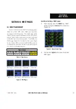
8.6  NEAREST USER WAYPOINT PAGE
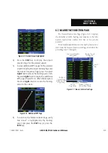
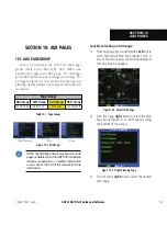
The Nearest 

1ÃiÀÊ7>Þ«œˆ˜ÌÊ*>}iÊ­ˆ}ÕÀiÊn‡£È®Ê`ˆÃ«>ÞÃÊ

the name, bearing, and distance to the nine nearest user 

Ü>Þ«œˆ˜ÌÃʭ܈̅ˆ˜ÊÓääʘ“ÊœvÊ̅iÊ«ÀiÃi˜ÌÊ«œÃˆÌˆœ˜®°

Figure 8-16  Nearest User Waypoint Page

Number of Pages in 

Current Page Group

Position of 

Current Page 

within Current 

Page Group

Current  

Page Group

Bearing To and 

Distance To

Waypoint Identifier 

and Symbol

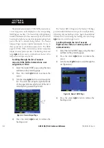
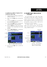
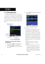
8.7  NEAREST CENTER (ARTCC) PAGE

/…iÊ  i>ÀiÃÌÊ i˜ÌiÀÊ *>}iÊ ­ˆ}ÕÀiÊ n‡£Ç®Ê `ˆÃ«>ÞÃʠ̅iÊ

facility name, bearing to, and distance to the five nearest 

,/Ê«œˆ˜ÌÃʜvÊVœ““Õ˜ˆV>̈œ˜Ê­ÜˆÌ…ˆ˜ÊÓääʘ“ÊœvÊ̅iÊ
«ÀiÃi˜ÌÊ «œÃˆÌˆœ˜®°Ê Ê œÀÊ i>V…Ê ,/Ê ˆÃÌi`]ʠ̅iÊ  i>ÀiÃÌÊ
i˜ÌiÀÊ*>}iÊ>ÃœÊˆ˜`ˆV>ÌiÃʜ˜iʜÀʓœÀiÊvÀiµÕi˜VˆiÃ]Ê>˜`Ê
“>ÞÊLiÊÕÃi`Ê̜ʵՈVŽÞÊÌ՘iÊ̅iÊ"ÊÌÀ>˜ÃViˆÛiÀÊ̜Ê̅iÊ

center’s frequency.  The selected frequency is placed in the 

ÃÌ>˜`LÞÊwi`ʜvÊ̅iÊ"Ê7ˆ˜`œÜÊ>˜`Ê>V̈Û>Ìi`ÊÕȘ}Ê̅iÊ

COM Flip-flop

 Key.

Figure 8-17  Nearest ARTCC Page

ARTCC Name

Frequency(ies)

Number of Pages in 

Current Page Group

Position of 

Current Page 

within Current 

Page Group

Current  

Page Group

Bearing To and 

Distance To


Содержание GNS 530

Страница 1: ...GNS 530 A Pilot s Guide and Reference...

Страница 2: ......

Страница 3: ...01 Update to reflect software changes through 2 06 C 4 03 Update to reflect software changes through 4 0 D 2 07 Updated layout added TAWS TERRAIN TIS and Weather information per SW v6 02 E 7 07 Updat...

Страница 4: ...this and other Garmin products Except as expressly provided herein no part of this manual may be reproduced copied transmitted disseminated downloaded or stored in any storage medium for any purpose...

Страница 5: ...Departure Page 7 14 7 8 Intersection Page 7 16 7 9 NDB Page 7 16 7 10 VOR Page 7 17 7 11 User Waypoint Page 7 18 SECTION 8 NRST PAGES 8 1 8 1 NRST Page Group 8 1 8 2 Nearest Airport Page 8 3 8 3 Near...

Страница 6: ...00 Rev G iv TABLE OF CONTENTS SECTION 16 MESSAGES ABBREVIATIONS and NAV TERMS 16 1 16 1 Messages 16 1 16 2 Abbreviations 16 9 16 3 Navigation Terms 16 12 Appendix A Data Card Use A 1 Appendix B Specif...

Страница 7: ...displayed by pressure altimeters in aircraft GPS altitude should never be used for vertical navigation Always use pressure altitude displayed by pressure altimeters in the aircraft WARNING The Jeppese...

Страница 8: ...in service center Unauthorized repairs or modifications could void both the warranty and the pilot s authority to operate this device under FAA FCC regulations NOTE All visual depictions contained wit...

Страница 9: ...DER ANY WARRANTY OF MERCHANTABILITY OR FITNESS FOR A PARTICULAR PURPOSE STATUTORY OR OTHERWISE THIS WARRANTY GIVES YOU SPECIFIC LEGAL RIGHTS WHICH MAY VARY FROM STATE TO STATE IN NO EVENT SHALL GARMIN...

Страница 10: ...GNS 530 A Pilot s Guide and Reference 190 00181 00 Rev G viii WARRANTY Blank Page...

Страница 11: ...U U i U V U iV U i U i U V ivi i Vi i U x i i i v Vi i i U L i L V V i U 7 i U x The Garmin dealer performs the installation and configuration of the GNS 530 The GNS 530 is secured in the installatio...

Страница 12: ...1 Keys and Knobs 4 2 6 5 1 10 11 14 15 16 17 18 3 7 8 9 12 13 19 COM Flip flop 1 Large left knob 6 ENT enter 11 MSG message 16 COM Power Volume 2 RNG map range 7 Small right knob 12 17 FPL flight plan...

Страница 13: ...i 8 Direct to Key i VVi i iV v V tion which allows the pilot to enter a destination waypoint and establishes a direct course to the selected destination iV 9 MENU Key V i i i v options This options li...

Страница 14: ...Row Keys 14 CDI Key 1 i i V Vi 6 i i i 15 OBS Key 1 i i iV V i i V v i i OBS Key selects i V i i V i V i as the navigation reference even after passing the waypoint i i i i i V i i i the OBS Key agai...

Страница 15: ...ation that is well away from buildings and other aircraft so the unit can collect satellite data without interruption This takeoff tour is intended to provide a brief introduction of the GNS 530 s maj...

Страница 16: ...ect to display Checklists Page Should Match Current OBS Course Selection Instrument Panel Self test Page Vi i L i Lii V i i i i i i v i i i i To ensure that the GNS 530 and any connected instruments a...

Страница 17: ...reduced over time based on the fuel flow figure Viewing the Checklists Page 1 Turn the large right knob to highlight Go To Chklist Figure 1 9 and press the ENT Key Figure 1 9 Go To Chklist Highlighted...

Страница 18: ...i v i i i acquiring satellite data to establish almanac and satellite orbit information which can take five to ten minutes The data is recollected from the first available satellite i i i i i V the m...

Страница 19: ...he kHz of the desired frequency Placing the standby communication frequency in the active field Press the COM Flip flop Key Figure 1 13 Figure 1 13 Active Frequency 135 325 MHz Vi i active frequency h...

Страница 20: ...e 1 14 Current Page and Page Group Current Page Group Number of Pages in Current Page Group Position of Current Page within Current Page Group Selecting the desired page group and page Turn the large...

Страница 21: ...many of the background map details by pressing the CLR i i i i i i i detail is depicted V i i i i i i v i RNG map i i i V i map range is depicted in the i iv V i v i Direct to Navigation The GNS 530...

Страница 22: ...direct to course to the selected destination Vi iV i i iV i i the CLR i i iv 6 i Default NAV Page y i iv 6 i i i i 6 i i i i i for navigation Selecting the Default NAV Page Press and hold the CLR Key...

Страница 23: ...NAV COM Page Frequency Type Departure Enroute or Arrival Airport Frequency List The 6 i i L i v i i V i V V v i i i any enroute airports which are included in the flight plan i w i 7 i i iV to functi...

Страница 24: ...ld in the COM or VLOCWindow COM frequencies automatically go to the standby field of the COMWindow and navigation frequencies automatically go to the standby field of the VLOC Window regardless of whi...

Страница 25: ...dures for the arrival when using approaches or STARs or departure when using SIDs airport 3 Turn the small right knob to select the desired procedure and press the ENT Key 4 For approaches a window ap...

Страница 26: ...v i 6 i i Vi i v i i V i L 6 wi L highlighting the frequency with the cursor and pressing the ENT Key Displaying the NRST pages 1 If necessary press and hold the CLR Key to select the NAV group and d...

Страница 27: ...Key to quickly set a course to a nearby facility in an in flight emergency Selecting a nearby airport as a direct to destination overrides the flight plan V Vi i i iV i iV i i pilot still has the opti...

Страница 28: ...i annunciator located directly above the MSG Key flashes to alert the pilot to the airspace i i ii iV i i Vi v information on enabling airspace alert messages Viewing an airspace alert message 1 Pres...

Страница 29: ...ht plan and V i v i questions about flight plans not found in this brief V V Li v iV x Creating a new flight plan 1 Press the FPL Key 2 Turn the small right knob to select the Flight Plan Catalog Page...

Страница 30: ...entered Figure 1 34 Figure 1 34 Enter Flight Plan Waypoints Vi i y V i i Li V i v i i i V i y Vi y V v i i i V V i Vi y V V i i y Activating the new flight plan 1 Press the MENU Key to display the Fl...

Страница 31: ...continuously Overriding the automatic squelch 1 Press the COM Power Volume Knob momentarily 2 Press the COM Power Volume Knob again to return to automatic squelch operation COM Window and Tuning Commu...

Страница 32: ...cy of 135 325 2 Turn the large left knob to select the desired megahertz MHz value For example the 135 portion of the frequency 135 325 3 Turn the small left knob to select the desired kilohertz kHz v...

Страница 33: ...the common traffic advisory frequency CTAF for each listed airport To select this frequency turn the large right knob to highlight the desired airport s CTAF frequency Figure 2 5 Figure 2 5 Nearest Ai...

Страница 34: ...1 Select the NAV COM Page from the NAV Page Group Section 3 1 or press and hold the CLR Key then turn the small right knob until the NAV COM Page appears 2 Press the small right knob to place the curs...

Страница 35: ...ight knob to highlight the desired frequency 6 Press the ENT Key to place the highlighted frequency in the standby COM Window field Emergency Channel The GNS 530 s emergency channel select provides V...

Страница 36: ...GNS 530 A Pilot s Guide and Reference 190 00181 00 Rev G 2 6 SECTION 2 COM Blank Page...

Страница 37: ...ently being displayed i 6 7 18 i Li v V ii L i V i L i i V and the placement of the current screen within that group V i L i i V Figure 3 1 Current Page and Page Group Current Page Group Number of Pag...

Страница 38: ...e information 3 3 DEFAULT NAV PAGE i w 6 i i iv 6 i i i iv 6 i i display with your present position at the bottom center of the page The top of the page displays desired track V Vi i i L v i i V i ii...

Страница 39: ...s TO a waypoint unless the OBS switch is set preventing automatic waypoint sequencing or if the aircraft has passed the last waypoint in the flight plan i i v i i i the bottom left corner Nine scale s...

Страница 40: ...ion has been selected only speed track altitude and minimum safe i Li i i i i L i i iv 6 i i is selected Selecting a different data item for any data field 1 Starting with the Default NAV Page press t...

Страница 41: ...nu 2 Turn the large right knob to highlight the Restore Defaults option Figure 3 7 and press the ENT Key Figure 3 7 Default NAV Page Menu Dual Unit Considerations w i v i iv 6 i vi iV i y iV x i i ii...

Страница 42: ...mbols are used to distinguish between waypoint types The identifiers for any on screen V Li i i i wi i i L i L iv iV i V i Vi boundaries appear on the map showing the individual iV v Vi Table 3 3 show...

Страница 43: ...Li i Vi i i V i Li i i v i 6 i Figure 3 10 Overzoom on Map Page i i i V Li iV i iw i i i V each map feature appears This provides the pilot with V i i V i V ii V i i can also quickly remove items from...

Страница 44: ...ounterclockwise 3 Turn the large right knob to move right turn clockwise or left counterclockwise 4 To cancel the panning function and return to the present position press the small right knob 7 i i t...

Страница 45: ...n be used anywhere on the v V i i i i i V i V i i created at the target pointer location before the direct to is initiated Airspace Information on the Map 7 i iV i V i Vi L i i i V V i i i v V y Vi V...

Страница 46: ...references including map orientation land data enable disable Jeppesen data enable disable V Vi L i i i NOTE Large medium and small classifications are used on the GNS 530 for airports and cities Larg...

Страница 47: ...e Map Display to a north heading c Select Track up Figure 3 19 to adjust the top of the Map Display to the current track heading Figure 3 19 Orientation Window d Press the ENT Key to accept the select...

Страница 48: ...field for the desired feature 4 Turn the small right knob to select the maximum range at which the feature should appear on screen or select Off to never display the selected feature 5 Press the ENT K...

Страница 49: ...2 Using Pointer to Measure Distance and Bearing 4 Again use the small and large right knobs to place the reference pointer at the desired location to measure TO The bearing and distance from the first...

Страница 50: ...t Change Fields Figure 3 24 and press the ENT Key Figure 3 24 Map Page Menu 2 Turn the large right knob to highlight the data field to be changed 3 Turn the small right knob to select the type of data...

Страница 51: ...relative to the aircraft altitude U i x x x U i V i i V i i v V up unless there is no valid heading U L V i U i V NOTE See Section 12 for a full description of TERRAIN functions Selectable Display Se...

Страница 52: ...ble on this page Seven display ranges are available allowing for a more complete view of the surrounding area Changing the display range Select theTERRAIN Page and press up or down on the RNG Key to s...

Страница 53: ...n is selected by default 2 Press the ENT Key The TERRAIN system is functional again TERRAIN Symbols NOTE See Section 12 2 for a complete description of TERRAIN symbology The following L i i i represen...

Страница 54: ...ttings The 7 i i iV L i i i U 6 i 6 i v L i V v i V i i i U 6 i 6 i v i i v either side of the aircraft flight path TAWS Page Indication Figure 3 34 TAWS Page GPS derived MSL Altitude Red Terrain Warn...

Страница 55: ...37 and press the ENT Key Pressing the CLR Key when theTAWS Page is displayed can also be used to toggle aviation information on or off Figure 3 37 TAWS Page Menu Inhibit Mode 7 L i i V i i i i V i i L...

Страница 56: ...s so as not to impede TAWS alerting TAWS Symbols NOTE See Section 13 2 for a complete description of TAWS symbology The following L i i i represent obstacles and potential impact points on the 7 i U i...

Страница 57: ...es in Current Page Group Position of Current Page within Current Page Group Current Page Group NOTE The order of the pages in the NAV Page Group change when the GNS 530 installation includes connectio...

Страница 58: ...Scroll Bar Scroll Bar 3 To place a frequency in the standby field of the COM or VLOC Window highlight the desired frequency and press the ENT Key Some listed frequencies may include designations for...

Страница 59: ...e The outer circle of the sky view represents the v i i i i V V i xc L i i i Vi i iV i head Each satellite has a 30 second data transmission that Li V iV i i L Liv i i i i Li i v signal strength L Vi...

Страница 60: ...e receiver uses satellite orbital data collected continuously from the satellites and last known position to determine which satellites should be in view 2D Navigation The GPS receiver is in 2D naviga...

Страница 61: ...e waypoint identifier field highlighted Figure 4 1 Select Direct to Waypoint Page 2 Use the small and large right knobs to enter the identifier of the desired destination waypoint Figure 4 2 Figure 4...

Страница 62: ...ars with the waypoint identifier field highlighted 2 Turn the large right knob to highlight the facility name second line or the city third line field Figure 4 5 Figure 4 5 Facility Name Highlighted 3...

Страница 63: ...The Select Direct to Waypoint Page appears with the waypoint identifier field highlighted 2 Turn the large right knob to highlight the flight plan FPL field Figure 4 7 Figure 4 7 Highlighted Flight P...

Страница 64: ...nine nearby airports Figure 4 9 Figure 4 9 Nearest Window 4 Continue turning the small right knob to scroll through the list and highlight the desired airport 5 Press the ENT Key to confirm the selec...

Страница 65: ...he location of the panning pointer Selecting a direct to destination from the Map Page 1 From the Map Page press the small right knob to display a panning pointer 2 Turn the small and large right knob...

Страница 66: ...Course to a Waypoint 7 i i v iV i x i iV great circle course to the selected destination The course to the destination can also be manually defined using the V i wi i i iV iV 7 i Manually defining th...

Страница 67: ...talog Page 5 1 FLIGHT PLAN CATALOG PAGE The i i V i i edit activate delete and copy flight plans Flight plans Li i v i i i flight plans v v i i i i i i V i v i y V i i v 7 i a flight plan is activated...

Страница 68: ...an 1 Press the FPL Key and turn the small right knob to display the Flight Plan Catalog Page 2 Press the small right knob to activate the cursor 3 Turn the large right knob to highlight the desired fl...

Страница 69: ...6 Once all changes have been made press the small right knob to return to the Flight Plan Catalog Page i i i V i Li i y plan which is displayed on the i i i y Li iv i y plan is being created the comm...

Страница 70: ...e Flight Plan and press the ENT Key Figure 5 10 Figure 5 10 Flight Plan Catalog Page Menu Inverting Flight Plans v i i y i to reverse the route for navigation guidance back to the original departure p...

Страница 71: ...By default the next empty catalog location is offered To select a different location turn the largerightknobtoselecttheflightplannumber use the small and large right knobs to enter a different number...

Страница 72: ...d press the ENT Key Auto automatically transfers the active flight plan or Direct to selection to another 400 or 500 series Garmin unit without user intervention 4 If Manual is selected Turn the large...

Страница 73: ...ans option from the Flight Plan Catalog Page Menu Figure 5 15 and press the ENT Key Figure 5 15 Flight Plan Catalog Page Menu 2 A confirmation window appears Figure 5 16 With Yes highlighted press the...

Страница 74: ...i V i i V i i i V v i y i v iV i x n i desired track Vi v i V i Figure 5 18 Active Flight Plan Page Active Flight Plan Options The options shown in Table 5 1 are available for the V i i Accessing the...

Страница 75: ...ction In many cases it is convenient to select approaches using the PROC Key as described in Section 6 1 Select Arrival Allows the pilot to select a published standard terminal arrival route STAR for...

Страница 76: ...s the ENT Key Figure 5 21 Select Field Type Window 5 Press the small right knob to remove the cursor Restoring factory default settings for data fields on the Active Flight Plan Page 1 With the Active...

Страница 77: ...ob to highlight the desired transition waypoint and press the ENT Key The Vectors option assumes the pilot will receive vectors to the final course segment of the approach and will provide navigation...

Страница 78: ...ing available transitions Figure 5 28 for the arrival Turn the small right knob to highlight the desired transition waypoint and press the ENT Key Figure 5 28 Transitions Window 4 With Load highlighte...

Страница 79: ...tive Flight Plan Page Menu Figure 5 30 and press the ENT Key Figure 5 30 Active Flight Plan Page Menu 2 A window appears with the reference waypoint field highlighted Use the small and large right kno...

Страница 80: ...ure or arrival to be deleted Titles appear in light blue directly above the procedure s waypoints Figure 5 32 Highlight Item To Be Deleted 3 Press the CLR Key to display a confirmation window Figure 5...

Страница 81: ...tivate Leg confirmation window Figure 5 35 Figure 5 35 Activate Leg Window 3 With Activate highlighted press the ENT Key 7 i i Vi i vi i V Li used not only to activate a specific point to point leg bu...

Страница 82: ...GNS 530 A Pilot s Guide and Reference 190 00181 00 Rev G 5 16 SECTION 5 FLIGHT PLANS Blank Page...

Страница 83: ...departure or arrival 1 Press the PROC Key to display the Procedures Page 2 Turn the large right knob to highlight Select Approach Select Departure or Select Arrival Figure 6 1 and press the ENT Key Fi...

Страница 84: ...rictly for monitoring only use theVLOC receivers and external CDI or HSI for primary navigation To confirm this reminder highlight Yes and press the ENT Key Not all approaches in the database are appr...

Страница 85: ...away enroute to the destination airport Later if vectored to final use the i L i i iV V i 6iV p V i i L V i i V i i i V i i v V i V i V 6 2 NON PRECISION APPROACH OPERATIONS The GNS 530 provides non p...

Страница 86: ...is places the approach in the active flight plan but retains course guidance in the enroute section until the approach is activated 4 Activate the full approach or vectors to final as appropriate In s...

Страница 87: ...the NAV COM Page Section 3 6 and Figure 6 9 and place it in the standby field of the COM Window Use the COM Flip flop Key to make the ATIS frequency active Figure 6 9 NAV COM Page 3 Press the PROC Ke...

Страница 88: ...e 6 13 Terminal Annunciator 2 Several miles prior to reaching the IAF LYH the pilot may wish to review the approach sequence Press the FPL Key to display the Active Flight Plan Page Press the small ri...

Страница 89: ...self is given The procedure turn is displayed on the Map Page and indicated as the active leg on the Default NAV Page and theActive Flight Plan Page The CDI needle starts moving to the right 7 When tu...

Страница 90: ...ional awareness only and should NOT be used for navigation Follow the published missed approach procedures 12 When approaching the MAP a waypoint alert APPRCHINGWPT appears in the lower right corner 1...

Страница 91: ...OR 3 An alert message in the lower right hand corner of the screen recommends entry procedures for the holding pattern i e HOLD DIRECT HOLD PARALLEL or HOLD TEARDROP see Figure 6 23 When flying the ho...

Страница 92: ...3 Press the ENT Key twice i i i iV i V i i i approach begins with a i i 9 intersection 4 Press the PROC Key and select the GPS 21 approach Section 6 1 for additional instructions 5 From the Transitio...

Страница 93: ...e holding pattern Figure 6 28 The timer can be used to fly the one minute outbound portion of the holding pattern The holding pattern is displayed on the Map Page and indicated as the active leg on th...

Страница 94: ...ght corner Figure 6 30 Make any course adjustments necessary for the final course segment FAF to MAP Figure 6 30 Final Approach 14 AftercrossingtheFAF thedestinationsequences to the MAP RW21 the runwa...

Страница 95: ...e missed approach sequence as outlined in this section Flying a DME Arc Approach i i v V V i additional Jeppesen provided waypoints to define the arc i i i V i L i w i i the waypoint name This is foll...

Страница 96: ...he Direct to Key or as the last waypoint in a flight plan Figure 6 33 Figure 6 33 Select Waypoint Page 2 Press the PROC Key and select the VOR 22 approach Figure 6 34 using the steps outlined in Secti...

Страница 97: ...the IAF approaches zero the alert is replaced by a turn advisory TURN TO 353 6 Follow the arc when the course select setting and desired track differ by more than 10 a Set course to message appears on...

Страница 98: ...e that the final course segment is displayed in magenta the active leg of the flight plan always appears in magenta and a dashed line extends the course beyond the MAP 11 When approaching the MAP a wa...

Страница 99: ...electing VECTORS from the Transitions Window 1 Select Billard Municipal KTOP as the destination using the Direct to Key or as the last waypoint in a flight plan 2 Press the PROC Key and select the VOR...

Страница 100: ...shed on the final V V i 7 i V V i i i i i v i w V V i i i i i V i active leg of the y 6 i v i active leg on i iv 6 i i i i V V i iV w DO NOT USE FOR NAVIGATION Figure 6 43 Terminal Mode i i i iV i iV...

Страница 101: ...final approach course Whenconvergingwiththefinalapproachcourse the needle moves toward the center In Figure 6 45 the needle has not yet returned to the on screen CDI since the current position is sti...

Страница 102: ...48 SUSP Annunciator Course From Fix Flight Plan Legs Certain approach departure and arrival procedures in the Jeppesen database contain V i v w y plan legs The GNS 530 is able to load these legs into...

Страница 103: ...Figure 6 51 Waypoint Alert Map Page 4 When approaching the intermediate fix CF25 a waypoint alert NEXT DTK 265 appears 5 Within 2 0 nm of the FAF THERO the GNS 530 switches from terminal mode to appr...

Страница 104: ...ith the course from fix to altitude leg The NEXT DTK 282 alert appears along the bottom of the screen 2 Note that within a few seconds of pressing the OBS Key to release suspend mode and start the app...

Страница 105: ...ttern entry procedure HOLD PARALLEL When flying the holding pattern a timer appears on the Default NAV Page The timer automatically resets on each outbound and inbound portion of the holding pattern F...

Страница 106: ...cedures Page then select the departure runway RW02 in this example and transition GEDIC Refer to Section 6 1 for instructions on selecting departures 2 When departing the airfield NEXT DTK 026 appears...

Страница 107: ...the 6 7 iv i v V ii i i 6 The GNS 530 can be set to automatically switch the i i v 6 i i i Vi i w V V i 7 i the ILS approach is activated the GNS 530 automatically V i iv v i w V V i V V i Vi i i v x...

Страница 108: ...o VLOC In this case press the CDI Key to manually switch from GPS to VLOC 2NM 15NM 1 2NM 1 2NM MANUAL FAF VLOC VLOC GPS GPS Figure 6 61 ILS Approach Selecting an ILS Approach i i i y v i i vv i iV i V...

Страница 109: ...ransitions Window select SHUTR as the IAF Figure 6 64 Also select Load or Activate if already cleared for the approach Figure 6 64 Transitions Window 4 A reminder message appears indicating that GPS c...

Страница 110: ...ot yet been activated in steps on the preceding page do so when cleared for the approach 3 When approaching the IAF SHUTR a waypoint alert NEXT DTK 030 appears along the bottom of the screen Figure 6...

Страница 111: ...ences to the inbound leg and NEXT DTK 210 appears along the bottom of the screen CDI coupling automatically switches from the GPS receiver to the VLOC Figure 6 69 receiver as the pilot completes the i...

Страница 112: ...mode is not activated for precision approaches since the VLOC receiver must be used for primary navigation Figure 6 70 CDI Scale Transition Figure 6 71 Final Approach Flagstaff DO NOT USE FOR NAVIGAT...

Страница 113: ...e CDI and Default NAV Page but course guidance along the final approach course continues Do not follow this extended course Follow published missed approach procedures using the OBS Key to initiate th...

Страница 114: ...mber for Localizer based Approaches U i iv v V i i V V v i iVi i i 6 iVi i v i i i V i i i i i i i iV 6 Vi i V i i Li 6 required for the final course segment from final V w U v i V V i v L i i V i 6 i...

Страница 115: ...the active frequency field by pressing the VLOC Flip flop i v i i iV appropriate frequency for approach message i v i U 7 i y V i L i V i L V V i V V enabled Vi i i y 1 outbound and on the initial po...

Страница 116: ...GNS 530 A Pilot s Guide and Reference 190 00181 00 Rev G SECTION 6 PROCEDURES 6 34 Blank Page...

Страница 117: ...this step may be skipped if the unit is already displaying any of the main pages 2 Turn the large right knob to select the WPT Page Group WPT appears along the bottom of the screen 3 Turn the small ri...

Страница 118: ...d then press the ENT Key 6 To remove the flashing cursor press the small right knob Entering a waypoint facility name or city location 1 Select the Airport Location Page NDB Page or VOR Page from the...

Страница 119: ...desired facility name or location following the preceding steps under To enter a waypoint facility name or city location 2 When spelling the facility name or location using the small and large right...

Страница 120: ...r press the small right knob 7 2 AIRPORT LOCATION PAGE The V i i i latitude longitude and elevation of the selected airport The V i v V i location as well as fuel availability available approaches rad...

Страница 121: ...Airport Location Page Options i v i L i v i V i L i i MENU Key U i iV i L i i V i i i i V v v i i airport in the active flight plan U i iV i L i i V i the pilot to view the location information for t...

Страница 122: ...unway Surface Runway Lighting Number of Pages in Current Page Group Position of Current Page within Current Page Group Current Page Group Displaying information for each additional runway 1 Press the...

Страница 123: ...i L i v i i L i i MENU Key U i iV i L i i V i i i i v v i i airport in the active flight plan U i iV i L i i V i i pilot to view the runway information for the active flight plan destination airport S...

Страница 124: ...Type Scrolling through the frequency list and tuning to a desired frequency on the list 1 Press the small right knob to activate the cursor 2 Turn the large right knob to scroll through the list plac...

Страница 125: ...e left of the desired frequency Figure 7 16 Figure 7 16 Info Highlighted 2 Press the ENT Key to display the restriction information Figure 7 17 Figure 7 17 Restriction Information Page 3 To return to...

Страница 126: ...r Destination Airport 7 5 AIRPORT APPROACH PAGE i V i i i available approach procedures for the selected airport 7 i i i V w i vii i routes are available that information may also be i i i v each appr...

Страница 127: ...t of the procedure name indicates the procedure can be flown using the GPS receiver Some procedures do not have this designation meaning the GPS receiver may be used for supplemental navigation guidan...

Страница 128: ...7 i i i transitions or runways are associated with the arrival Vi i v Li i map image provides a layout diagram for each arrival transition and runway To view arrival information for a particular airpo...

Страница 129: ...s Window 6 Press the ENT Key The cursor moves to the runway field 7 Turn the small right knob to display a window of available runways Figure 7 26 Continue turning the small right knob to select the d...

Страница 130: ...port Arrival Page Menu 4 TheActive Flight Plan Page appears Press the FPL Key to return to the Airport Arrival Page i iV v i i v i i i v i iVi i L i iV the desired option in step 3 7 7 AIRPORT DEPARTU...

Страница 131: ...display a window of available transitions Continue turning the small right knob to select the desired transition 8 Press the ENT Key To remove the flashing cursor press the small right knob Airport De...

Страница 132: ...iV 1 1 U v i i 6 i ii i V i ii i i i V w U Vi v i i 6 V i i i i i i i V w NOTE The VOR displayed on the Intersection Page is the nearestVOR not necessarily theVOR used to define the intersection 7 9...

Страница 133: ...ed U L ii iV v V v L i 6 symbols U 6 i V i ii U i i i ii i i ii i iV 1 1 U i i V i i U 7 V 7i i v L V the selected facility s frequency i i iV 6 Li i iV i L i wi v V i V V i 6 i Li i V i i 6 iVi i i i...

Страница 134: ...erence waypoint in degrees i V i ii i i i V w U Vi v reference waypoint in V i i i i i i i V w U i i i ii i i ii i iV 1 1 1 i Li i iV i L i i wi i V Li iV Creating User Waypoints 1 i Li V i i v i 1 i...

Страница 135: ...ght knob to activate the cursor 2 Use the small and large right knobs to enter a name for the new waypoint and press the ENT Key 3 Turn the large right knob to highlight the first reference waypoint R...

Страница 136: ...nearestVOR However the pilot can select any waypoint by identifier to use as a reference in this field The GNS 530 can store user defined waypoints which are generated from other equipment in the pane...

Страница 137: ...small right knob to remove the flashing cursor Modifying a user waypoint by changing reference waypoint information 1 With the User Waypoint Page displayed press the small right knob to activate the c...

Страница 138: ...ge The pilot must first cancel the direct to or remove the waypoint s from the active flight plan before modifying or deleting the waypoint s User Waypoint Page Options Thefollowing1 i 7 i i L i by pr...

Страница 139: ...ify rename or delete a selected user waypoint or to delete all user waypoints currently stored in memory The top of the page shows the number of waypoints used and available memory Reviewing and or mo...

Страница 140: ...y to accept the new name Figure 7 47 User Waypoint Name Selected 4 A rename waypoint confirmation window is displayed Figure 7 48 With Yes highlighted press the ENT Key to rename the selected user way...

Страница 141: ...ction 2 Press the MENU Key to display a menu for the User Waypoint List Figure 7 50 Figure 7 50 User Waypoint List Page Menu 3 With Delete All User Waypoints highlighted press the ENT Key 4 A delete a...

Страница 142: ...GNS 530 A Pilot s Guide and Reference 190 00181 00 Rev G 7 26 SECTION 7 WPT PAGES Blank Page...

Страница 143: ...lus alerts the pilot to any nearby Special 1 i 1 i Vi Table 8 1 Page Groups Page Groups NAV Group WPT Group AUX Group NRST Group see Section 3 see Section 7 see Section 10 8 NRST pages Figure 8 1 NRST...

Страница 144: ...e desired NRST page using the steps outlined on the preceding page 2 Press the small right knob to activate the cursor 3 Turn the large right knob to scroll through the list The scroll bar along the r...

Страница 145: ...elect Direct to Waypoint Page 3 Press the ENT Key to accept the selected waypoint s identifier and press the ENT Key a second time with Activate highlighted to begin navigating to the selected waypoin...

Страница 146: ...e 8 7 Figure 8 7 Frequency Moved to Standby Field Standby Frequency Field Selected Frequency 5 Press the COM Flip flop Key to activate the selected frequency Figure 8 8 Active Frequency Field Figure 8...

Страница 147: ...hed press the small right knob to return the flashing cursor to the screen Figure 8 10 Additional WPT Page 6 To return to the Nearest Airport Page verify that Done is highlighted by the flashing curso...

Страница 148: ...in Current Page Group Current Page Group Bearing To and Distance To Intersection Identifier and Symbol NDB Frequency 8 5 NEAREST VOR PAGE The i i 6 i i n i identifier symbol bearing and distance to th...

Страница 149: ...OC Window 5 Press the VLOC Flip flop Key to activate the selected frequency 6 Press the small right knob to remove the flashing cursor Viewing additional information for a nearby VOR 1 Select the Near...

Страница 150: ...ent Page Group Bearing To and Distance To Waypoint Identifier and Symbol 8 7 NEAREST CENTER ARTCC PAGE i i i i i i i n i facility name bearing to and distance to the five nearest v V V v i i i i V i i...

Страница 151: ...s the COM Flip flop Key to activate the selected frequency Figure 8 18 Figure 8 18 Frequency Moved to Active Field Selected Frequency Active Frequency Field 7 Press the small right knob to remove the...

Страница 152: ...g the desired FSS 4 Turn the large right knob to scroll down the page Figure 8 20 highlighting the desired frequency COM frequency or VOR frequency for duplex operation Selected Frequency Figure 8 20...

Страница 153: ...v Vi Figure 8 22 Airspace Message U v i V v V i v airspace and the current course will not take the V v i i i i i Vi i i i n i i i Vi i i Vi i Figure 8 23 Airspace Message U v i V v i i i Vi i i i i...

Страница 154: ...an airspace listed on the Nearest Airspace Page 1 Select the Nearest Airspace Page using the steps outlined in Section 8 1 2 Press the small right knob to activate the cursor 3 Turn the large right k...

Страница 155: ...ght knob to scroll through the list highlighting the desired frequency 4 Press the ENT Key to place the selected frequency in the standby field of the COM Window Figure 8 27 Figure 8 27 Airport Freque...

Страница 156: ...i U i V i U U U U 1 iV wi U 7 i L V i v i Vi i displays the floor and ceiling limits of the airspace The v i i i v i i V limits for an airspace U x v x vii i i i i U x v x vii L i i i U i i i i U Vi i...

Страница 157: ...ndow and Tuning 6 v i i V i i i i i left knobs i i V i L 6 frequency field The standby frequency always appears below the active frequency The active frequency is the frequency currently in use The tu...

Страница 158: ...L V i i 6 i 7 i i wi V i i 6 i 7 V Li i Vi with traffic information or configurable data fields as i iV Auto Tuning frequency may also be quickly selected from the database by simply highlighting the...

Страница 159: ...edures is provided in Section 6 1 To select an approach and automatically tune the proper VLOC frequency 1 Select the destination airport using the Direct to Key or as the last waypoint in the active...

Страница 160: ...the external CDI or HSI press the CDI Key and verify that VLOC is displayed at the bottom left corner of the screen directly above the CLR Key 8 For precision approaches and some non precision approa...

Страница 161: ...0 1 AUX Pages Flight Planning Utility Setup NOTE The AUX Page Group may have four AUX pages available when the GNS 530 installation includes connection to a weather information source See Section 14 o...

Страница 162: ...e 10 4 2 Turn the large right knob to select the desired menu option 3 Press the ENT Key Figure 10 5 to display the desired page Figure 10 5 Density Alt TAS Winds Page The following menu options are a...

Страница 163: ...t is current GPS calculated ground speed entered on the Fuel Planning Page automatically transfers to theTrip Planning Page and vice versa U i 7 V i i theoretical altitude at which the aircraft can pe...

Страница 164: ...anning Figure 10 6 turn the small and large right knobs to enter the identifier of the from waypoint Once the waypoint s identifier is entered press the ENT Key to accept the waypoint The flashing cur...

Страница 165: ...the ENT Key to select the data configuration Flight Planning Page Trip Planning Performing trip planning operations 1 Select Trip Planning from the Flight Planning Page using the steps described in t...

Страница 166: ...E Estimated time enroute ETA Estimated time of arrival Flight Planning Page Density Alt TAS Winds Calculating density altitude true airspeed and winds aloft 1 Select Density Alt TAS Winds from the Fli...

Страница 167: ...ata sensor to provide any of the variables above the DensityAlt TAS Winds Page data defaults to the values provided by these components Flight Planning Page Scheduler Entering a scheduled message 1 Se...

Страница 168: ...the old figure Press the ENT Key when finished Deleting a scheduled message 1 Select Scheduler fromtheFlightPlanningPage using the steps described in this section 2 The flashing cursor highlights the...

Страница 169: ...ion or active flight plan to a second 400 500 series Garmin unit Figure 10 13 Crossfill Method Window NOTE Crossfill requires both 400 500 series units to have the same Jeppesen NavData database cycle...

Страница 170: ...cursor moves to the CROSS SIDE field Turn the small right knob to select To or From and press the ENT Key 8 The flashing cursor moves to the Initiate Transfer confirmation field Press the ENT Key to...

Страница 171: ...or only when ground speed i Vii U V i i v i i i i ii ii i i i i i i L i Vi L i i MENU Key to display the V i i U i V i V v V i i available for the current location or at a specified waypoint at any t...

Страница 172: ...ility Page Checklists Creating a checklist 1 Select Checklist from the Utility Page using the steps described at the beginning of this section 10 3 Press the ENT Key to display a list of checklists 2...

Страница 173: ...T Key when finished Inserting a checklist step into an existing checklist 1 With the Checklists Page displayed turn the large right knob to select the desired checklist and press the ENT Key 2 Turn th...

Страница 174: ...eric timer 1 Select Flight Timers from the Utility Page using the steps described at the beginning of this section 10 3 2 The flashing cursor highlights Start To start the generic timer press the ENT...

Страница 175: ...s a departure time once the GPS computed ground speed exceeds 30 knots Figure 10 21 Departure Reset Mode Window 4 Press the ENT Key when finished 5 To reset the departure time turn the largeright knob...

Страница 176: ...Predicting RAIM availability 1 Select RAIM Prediction from the Utility Page using the steps described at the beginning of this section 2 The flashing cursor highlights the waypoint field Use the small...

Страница 177: ...rage within 15 minutes of the specified arrival date and time Refer to Section 10 4 for specific information regarding RAIM protection limits also refer to Section 15 for FDE Fault Detection and Exclu...

Страница 178: ...user functions are available from this page Figure 10 27 Terrain Database Versions Page 10 4 SETUP PAGE i i i i n i VVi i Vi V i i arrival alarm units of measure settings position formats i v V 1 i 7...

Страница 179: ...esent full scale iyiV v i i i i i i iv i setting the V i i x i i i Vi V i v y 7 of the destination airport the V i i i i i when leaving the departure airport the V i i 1 x Li v i i i V i i V i gradual...

Страница 180: ...sage if the aircraft is less than 500 feet above or below an airspace and projected to enter it the pilot is notified i i i i iv vii U 1 i V w i the displayed data to standard or metric units of measu...

Страница 181: ...data wi iV Li i 6 7 L i i 6 V w L i wi v V ii V Vi i v i GNS 530 is interfaced with a traffic information i Vi ii iV L vwV V Li configured for display in the data field U w i i iV n x v i i V V i V NO...

Страница 182: ...Scale Alarms Changing the maximum CDI scale 1 Select CDI Alarms from the Setup Page using the steps described at the beginning of this section 2 The flashing cursor highlights the Selected CDI field F...

Страница 183: ...nce 1 Select CDI Alarms from the Setup Page using the steps described at the beginning of this section 2 Turn the large right knob to highlight the On Off field directly below Arrival Alarm 3 Turn the...

Страница 184: ...se the small and large right knobs to enter the desired magnetic variation direction and value Press the ENT Key when finished Changing the units of measure 1 Select Units Position from the Setup Page...

Страница 185: ...n Format Window 3 Turn the small right knob to select the desired position format The following position formats are available degrees and decimal minutes degrees minutes and decimal seconds Universal...

Страница 186: ...s the ENT Key to accept the selection Setting the local time 1 Select Date Time from the Setup Page using the steps described at the beginning of this section 2 Turn the large right knob to highlight...

Страница 187: ...rn the small right knob to select the desired level Press the ENT Key to accept the selection Setup Page Nearest Airport Criteria Setting the minimum runway length and runway surface 1 Select Nearest...

Страница 188: ...OTE The Traffic selection in the Auxiliary Configuration Field is only available if the GNS 530 is configured for interface with a traffic information device see Section 14 3 Press the ENT Key to acce...

Страница 189: ...sired channel spacing 8 33 kHz or 25 0 kHz Press the ENT Key when finished Figure 10 44 Channel Spacing Window Restoring Factory Settings 7 i V i i i i i iv i i iV i i i i v V i v i i iV i i i i i i i...

Страница 190: ...GNS 530 A Pilot s Guide and Reference 190 00181 00 Rev G 10 30 SECTION 10 AUX PAGES Blank Page...

Страница 191: ...cal navigation features the ground speed must be greater than 35 knots and direct to navigation or a flight plan must be activated Figure 11 1 VNAV Profile V E R T I C A L N A V I G A T I O N P R O F...

Страница 192: ...t a distance from the target reference waypoint and press the ENT Key If the target altitude should occur at the target reference waypoint enter a distance of zero 6 Turn the small right knob to selec...

Страница 193: ...ation feature U i i i V i i Vi i i V 6 6 w i i x VV i i Vi V L angle also locks to prevent changes in speed from altering the profile Figure 11 5 VNAV Profile Message U v i iV i i i V ii i i 6 i i iv...

Страница 194: ...sages 1 Press the MENU Key to display the Vertical Navigation Page Options menu Figure 11 7 Figure 11 7 VNAV Page Options Menu 2 With VNAV Messages On highlighted press the ENT Key Or if the messages...

Страница 195: ...OTE The data contained in the TERRAIN databases comes from government agencies Garmin accurately processes and cross validates the data but cannot guarantee the accuracy and completeness of the data i...

Страница 196: ...i V V i i V i V v y i to the surrounding terrain and obstacles In this manner V i Vi i v i V i i i V i i i i i described later in this section Baro Corrected Altitude V iV i i V i i i i by adjusting t...

Страница 197: ...e aircraft altitude Black Terrain between 100 ft and 1000 ft below the aircraft altitude Yellow Terrain above or within 100 ft below the aircraft altitude Red Figure 12 1 Terrain Altitude Color Correl...

Страница 198: ...Field NOTE TERRAIN Advisory Alerts are displayed as constant black text on a yellow background TERRAIN CautionAlerts are displayed as flashing black text on a yellow background i i i E V i i L i i i...

Страница 199: ...arance RTC Advisory Required Terrain Clearance RTC Caution FLASHING FLASHING Imminent Terrain Impact ITI Advisory Imminent Terrain Impact ITI Caution FLASHING FLASHING Required Obstacle Clearance ROC...

Страница 200: ...i i i i Vi i Vi i i L V i i Vi i i i i issued when the aircraft flight path is above terrain yet is projected to come within the minimum clearance i L i 7 i i i i V i i i U i i V i L V i V i i i i i i...

Страница 201: ...Low Terrain Runway Threshold Figure 12 5 PDA Alerting Threshold TERRAIN Inhibit L i i V i i i i V i i L i i Li i L i i system when appropriate Inhibiting TERRAIN 1 Select theTERRAIN Page and press th...

Страница 202: ...ecome degraded or if the aircraft is out of the database coverage area the annunciation i i i i V 6 i i i i i i n 7 i i i i L i and the aircraft is within the database coverage area the V i i Figure 1...

Страница 203: ...nment agencies Garmin accurately processes and cross validates the data but cannot guarantee the accuracy and completeness of the data The terrain obstacle databases are contained on a datacard which...

Страница 204: ...nsert the new card into the right most slot of the GNS 530 4 Turn on the GNS 530 and verify that the TERRAIN system passes self test Terrain Obstacle Database Areas of Coverage L i x i i v V i i L i i...

Страница 205: ...nnot guarantee the accuracy and completeness of the data 7 i L V i i i altitude of the aircraft The displayed caution and warning alerts are advisory in nature only Individual obstructions Li v L i i...

Страница 206: ...iV i i V i i i i by adjusting the altimeter setting for local atmospheric conditions The most accurate baro corrected altitude can be achieved by frequently updating the altimeter setting to the near...

Страница 207: ...t below the aircraft altitude Black Terrain between 100 ft and 1000 ft below the aircraft altitude Yellow Terrain above or within 100 ft below the aircraft altitude Red Figure 13 1 Terrain Altitude Co...

Страница 208: ...ledges the pop up alert and returns to the currently viewed page U i i ENT Key This acknowledges the i VVi i i 7 i NOTE To further capture the attention of the pilot TAWS issues aural voice messages t...

Страница 209: ...t IOI Warning or Obstacle Ahead Pull Up Obstacle Ahead Pull Up or Obstacle Obstacle Pull Up Pull Up Reduced Required Terrain Clearance RTC Caution or Caution Terrain Caution Terrain or Terrain Ahead T...

Страница 210: ...3 Additional System Annunciations Forward Looking Terrain Avoidance i i Vi i i L 7 V i v U i Vi i i i i Vi i Vi i i L V i i Vi i i i i issued when the aircraft flight path is above terrain yet is pro...

Страница 211: ...rrain Too Low Terrain Runway Threshold Figure 13 5 PDA Alerting Threshold TAWS Inhibit 7 L i i V i i i i V i i L 7 i i Li i L i i i i i i i i L i i L i Inhibiting TAWS 1 Select theTAWS Page and press...

Страница 212: ...i i v i Vi i i Vi i i i L i wV i i V v i i i Li V i Vi i i Vi i ii i n i i i v i i iw i L x L 6000 5500 5000 4500 4000 3500 3000 2500 2000 1500 1000 500 0 2000 4000 6000 8000 10000 12000 PULL UP PULL...

Страница 213: ...when the following condi tions are met U i i L i i i i vii U i Vi v i i i i U i i V i v i i i i v i i i i ii i w i V i i i i i iw i L x L i i i i i i i i i i i w w i i i i i i i V ii i i i i i iV w i...

Страница 214: ...ge TAWS NOT AVAILABLE ALERT 7 i i with specific vertical accuracy minimums Should the navigationsolutionbecomedegradedoriftheaircraftisout v i L i V i i i i V i i i i V 6 i i i i 7 i i i i i L i i i i...

Страница 215: ...gencies Garmin accurately processes and cross validates the data but cannot guarantee the accuracy and completeness of the data The terrain obstacle databases are contained on a datacard which is inse...

Страница 216: ...d into the right most slot of the 500 Series unit 4 Turn on the GNS 530 and verify that theTAWS system passes self test Terrain Obstacle Database Areas of Coverage Table 13 5 lists the area of coverag...

Страница 217: ...adar Site Map covering the U S NOTE This Section assumes the user has experi ence operating the GNS 530 and the Garmin GTX 330 Transponder NOTE TIS and Weather Data Link displays are availableonlywhen...

Страница 218: ...ve maneuvers TIS Limitations NOTE This section on TIS Limitations is not comprehensive Garmin recommends the user review the TIS Limitations section of the Aeronautical Information Manual Section 1 3...

Страница 219: ...induce errors in the GNS 530 display These errors primarily affect relative bearing information and traffic i V iV i Vi i remain relatively accurate and may be used to assist in ii i v i i V i i v the...

Страница 220: ...rding L V i i V i i i i i L L i i vwV L i i V V i v V V i i i i v i vwV i i i v i i V i vwV i i vwV i i vwV i diamond i i v V i V v i i i v vii v i V i L v traffic is above own aircraft altitude the d...

Страница 221: ...rack Vector Figure 14 3 Out of Range TA Symbol Out of Range Traffic Advisory TA Symbol Figure 14 4 Altitude Trend and Deviation Altitude Deviation Altitude Trend Traffic Page TIS Traffic data is displ...

Страница 222: ...condition Figure 14 6 Traffic Age Indicator and Coasting Banner Traffic Coasting Banner and Age Indicator U i i Li iVi i v 8 i but there was a failure detected in the data stream The pilot should see...

Страница 223: ...ut not shown Figure 14 11 Traffic Removed Banner Traffic Removed Banner and Age Indicator 1 6 7 i iV i i i no data TIS is considered to be unavailable This i V i L i i 1 6 i i Li i 1 6 could indicate...

Страница 224: ...U L V i i i i V v L i Li i V i V v U i vvi i Vi i i v vii Li ii i i V v i V i aircraft U V i i aircraft is climbing or descending at a rate greater than 500 fpm Traffic Page Display Range Various disp...

Страница 225: ...the step for Traffic Symbol and Traffic Label 5 Press the CLR Key to return the Map Page The traffic mode selection menu allows the user to choose from the following vV vwV i i i vwV i i i i i i i V...

Страница 226: ...unction and return to the present position press the small right knob 7 i i i i Vi vwV i vwV i i i i i i n Figure 14 18 Traffic Range and Altitude Separation Traffic Range and Altitude Separation Targ...

Страница 227: ...nd highlight OPER 2 Turn the small right knob to select STBY 3 Press the ENT Key to confirm Flight Procedures Vi i V v L i i i i L i V w i i v i i switches from standby mode to operating mode The x i...

Страница 228: ...using bursts of compressed i v n L 7i i i i i iV i v i 8 Satellite Radio network The following operational differences are noted Li ii i i 8 V iV i L i 7i i i Vi i i i i i i v i This data is then deli...

Страница 229: ...en the radar antenna points directly at the sun V v i i V V vv V can cause alterations in radar scans Interference from buildings or mountains which may cause shadows NEXRAD Limitations CAUTION NEXRAD...

Страница 230: ...Very Light 5 00 trace 10 Light 10 0 trace 10 Light Light 15 01 1 2 Light Light 20 02 2 3 Light Light 25 05 3 5 Light Light Medium 30 09 5 7 Light Moderate Moderate 35 24 7 1 0 Moderate Heavy 40 48 1...

Страница 231: ...cify reference points for the request The following w i i L i v i i i wi i i i 8 v the aircraft s current position i i i 8 i v i V i i i i 8 v iV wV i wi v selected as the reference point for the requ...

Страница 232: ...y The request has been sent Note that selecting Auto Request and pressing the ENT Key does not send the request until after the auto time period 6 To exit from the NEXRAD Request Page press the small...

Страница 233: ...nob and select NEXRAD 4 Press the small right knob Customizing NEXRAD Data on the Weather Page i V V i i 8 i 7i i i v i i i Customizing the NEXRAD data on the Weather Page 1 From the Weather Page pres...

Страница 234: ...nob to set the density desired i e the transparency see Table 14 4 of the NEXRAD cells The density values are LOW MED HIGH Press the ENT Key to make the selection then press the CLR Key to go back to...

Страница 235: ...LR Key is pressed while density is set to low Request Shortcuts i V V i iV i 8 i i v iV wV v i V i Three methods of selecting the Airport Location Page right knobs to select theAirport Location Page f...

Страница 236: ...ss the ENT Key Figure 14 26 Data Link Page 3 The Data Link Request Log Page is displayed Figure 14 27 Figure 14 27 Data Link Request Log Page Sending Position Reports GDL 49 Only i v VV i V V v the ai...

Страница 237: ...in order to take advantage of EchoFlight s Automatic Weather Delivery AWD service the time interval must be set to 15 minutes current single position report Figure 14 29 Figure 14 29 Position Report...

Страница 238: ...when an active Flight Lii i iV i i wi i Vi v i i iV which waypoint in the active flight plan to use as the reference point for the request V i i wi i iV i i v x x V miles from the selected position 7...

Страница 239: ...The request has been sent Note that selecting Auto Request and pressing the ENT Key does not send the request until after the auto time period 6 To exit from the METAR Request Page press the small ri...

Страница 240: ...to select METAR WINDS or TEMP DP 3 Press the MENU Key TheWeather Page Menu is displayed 4 Turn the small right knob highlight Display Legend and press the ENT Key The Weather Legend is displayed Figur...

Страница 241: ...his airport press the MENU key to access the page menu and select Request METAR 6 The METAR Request Page is displayed The request option is displayed on the Textual METAR Page Displaying Wind Data Dis...

Страница 242: ...on i iV i i L i i clear indication of any potential internal failures If no V i V iV i V V L i i i iV V V iV i i i the unit has power applied Repair stations are equipped i i i i v i i Monitoring the...

Страница 243: ...with the GDL 49 has been lost Idle Waiting to perform the next task Receiving message Receiving a response from the satellite Sending message Transmitting a message Sending request Transmitting a req...

Страница 244: ...ons The standard aviation forecast abbreviations are listed L i STANDARD AVIATION FORECAST ABBREVIATIONS Heavy Light Missing or separator Axxxx Altimeter setting xxxx are numbers AFT After BKN Broken...

Страница 245: ...61 minutes Yellow Unknown Yellow Table 14 10 Weather Age Graphics METARs Precipitation Graphics Light Green Moderate Green Heavy Yellow No Precipitation Rain Snow Unknown Table 14 11 Precipitation Gra...

Страница 246: ...et Blank Gusts are unknown or 5 kts above sustained wind speed G10 Green Wind is gusting 5 10 kts more than sustained speed G11 Yellow Wind is gusting 11 kts or more above its sustained speed Table 14...

Страница 247: ...re Dewpoints i i i i i i L L i x i vvi i Vi Li ii i i i i i i i vvi i Vi i degrees Fahrenheit Temp Dewpoint Display Ranges Blank Unknown 11 Green 7 10 Green 0 6 Yellow Table 14 15 Temp Dewpoint Ranges...

Страница 248: ...GNS 530 A Pilot s Guide and Reference 190 00181 00 Rev G 14 32 SECTION 14 ADDITIONAL FEATURES Blank Page...

Страница 249: ...arture 15 1 DETECTION AND EXCLUSION V v V v i iV v i V i i iV v V ivi the capability to detect a satellite failure which can affect 1 i iV i i V v V i V i i i v i i i i i i v Li i i return to normal p...

Страница 250: ...v i i i V i i L i i i V Li performed prior to departure for a flight involving U Vi V i i i i i Li i i Vi v i Vi n U 1 i 6 i i i i i i v V i i i i i V i i Li v i Vi i 1 i i i 6 i i i i i i i i V i i...

Страница 251: ...of an arrival airport when an approach is loaded All data referenced to True North The GNS x i iV i V i iv data card slot Altitude input failure The GNS 530 is V w i iVi i i i i V i Li iVi i i Li iVi...

Страница 252: ...responding Internal system to system communication between the main Vi i Vi i v i i v i Vi i unknown and the unit should be returned to a Garmin dealer for service COM needs service The GNS 530 has d...

Страница 253: ...V i departures or arrivals have been modified from i L i v 7 i i V i Vi L i i i V i the new database must be manually verified This message occurs each time a flight plan containing wi Vi i i i i v L...

Страница 254: ...iVi i not available and the unit should be returned to a Garmin dealer for service GPS is not responding Internal system to system communication between the main Vi i iVi i v i i v i iVi i and the un...

Страница 255: ...i i i v the altitude is in error by more than 500 feet enter the current altitude as accurately as possible VV i i iV i inaccurate position information No altitude input is being received No i Li iVi...

Страница 256: ...elect an alternate source for navigation guidance such as the GNS x 6 iVi i v 6 V i L i V RAIM position warning vwV i i i V i i i iVi i i determined the information from one or more i i Li i i i Li i...

Страница 257: ...figuration Terrain has failed The terrain functionality self test has failed The operational status of the terrain components is unknown and the unit should be returned to a Garmin dealer for service...

Страница 258: ...Try pressing the VLOC Flip flop Key again to cycle its operation If the message persists contact a Garmin dealer for assistance Waypoint already exists The name just i i i v i i i memory Waypoint s h...

Страница 259: ...AVTN BARO i V i i BRG Bearing To C i ii i C V 6 CAS L i ii CDI i i V CLR Clear COM Communications Transceiver CRSR Cursor CTA i CTAF vwV i i V CTR i i CTS Course To Steer CUM Cumulative DB L i DEN i...

Страница 260: ...nt Landing System IND Indicated INT Intersection INTEG Integrity kg Kilograms kHz i km Kilometers kph i i i kt Knots LAT LON Latitude Longitude lb LCL Local LFOB iv i i LOC V i LRES Left over Fuel Res...

Страница 261: ...D i i i Sml Small SPD Speed SQ Squelch SRFC Surface STAR i i SUA iV 1 i Vi T i ii i TACAN V V TAS i ii TAT i i i TEMP Temperature TERM Terminal TKE V i TMA i i TRANS Transition TRFC Traffic TRK V V TR...

Страница 262: ...dicated airspeed corrected for instrument errors CTS course to steer The recommended direction to steer in order to reduce course error V i i i ivwV i heading to get back to the desired course and pro...

Страница 263: ...n in the V v i i V i i LFOB left over fuel onboard The amount of fuel remaining on board after the completion of a i i i v y iV LRES left over fuel reserve The amount of fuel remaining on board after...

Страница 264: ...GNS 530 A Pilot s Guide and Reference 190 00181 00 Rev G SECTION 16 MESSAGES ABBREVIATIONS NAV TERMS 16 14 Blank Page...

Страница 265: ...hand slot NOTE There are two data card slots on the face of the GNS 530 Figure A 1 The Jeppesen NavData card should be inserted in the left hand slot The right hand slot is provided for the Terrain Da...

Страница 266: ...er of the data card This partially deploys the swing arm handle Press here to deploy handle Figure A 3 Swing Arm Handle Operation 2 Rotate the swing arm handle outward until it locks into place perpen...

Страница 267: ...i V i i V V i iV x iV V 1 i i Vi i iV V VV V x i i v 6i V i i V i V VVi i VHF COM PERFORMANCE C i x V n n V i i V i n x i x x VOR PERFORMANCE i i V i n x LOCALIZER PERFORMANCE i i V i n x GLIDESLOPE...

Страница 268: ...GNS 530 A Pilot s Guide and Reference 190 00181 00 Rev G APPENDIX B SPECIFICATIONS B 2 Blank Page...

Страница 269: ...V i V V iV V i i i i i that the available satellite geometry allows the receiver to calculate a position within a specified protection limit v Vi V v i i v i v iV V i Vi V i i i i v y L i i v i i iV i...

Страница 270: ...ion from the current database to definethewaypoints Ifthedatabaseischangedorupdated the GNS 530 automatically updates the information if the procedure has not been modified If an approach departure or...

Страница 271: ...i i V v i i Vi i V v V i i V i i i V i i ivi iV v i i the OBS Key i V v i OBS Key is holding patterns The OBS Key is used to suspend waypoint sequencing and select the desired course along the waypoi...

Страница 272: ...uence to the next waypoint The GNS 530 only sequences flight plan waypoints i V i i V i L i i 1 V iV L i i OBS i automatic sequencing to occur the aircraft must also cross i L iV v i Li i i L iV a per...

Страница 273: ...v Li i i i i i i Li i i V i flips momentarily to indicate that the aircraft has crossed the midpoint of the turn For more information on waypoint alerts and turn i ii iV When does the CDI scale change...

Страница 274: ...re select the same approach or activate a new approach after a missed approach v i y missed approach procedures the pilot mayreactivatethesameapproachforanotherattemptfrom i Vi i i Vi i V i Vi v i at...

Страница 275: ...19 B Backlighting 10 20 10 27 16 2 16 3 Bearing 1 6 1 11 3 4 3 8 3 13 3 14 5 9 5 13 8 3 8 5 8 6 8 8 8 9 16 9 16 12 Bottom Row Keys 1 4 C CAUTIONS vi CDI key 1 4 6 26 6 31 6 32 9 4 16 2 16 7 CDI scale...

Страница 276: ...17 1 18 2 1 2 5 3 10 3 21 3 22 6 2 6 5 6 25 6 27 6 28 6 29 6 33 7 8 7 9 7 11 7 16 7 17 8 7 8 9 8 10 8 13 9 1 9 4 16 6 16 7 Frequency selection 9 1 Fuel planning 10 1 10 4 Full Screen Map 3 13 G GDL 49...

Страница 277: ...Page Group 1 5 2 4 3 2 NDB 1 11 1 16 3 6 6 3 7 2 7 5 7 16 7 17 7 18 7 19 7 21 8 3 8 6 16 10 Nearest NRST Pages 1 16 Nearest airport criteria 10 21 10 27 10 28 Nearest Airport Page 1 16 1 17 2 3 8 2 8...

Страница 278: ...1 Squelch 2 1 16 11 Standby Frequency 1 9 2 2 8 9 8 10 STARs 1 15 15 2 Stuck Microphone 2 5 SUSP 6 8 6 11 6 13 6 16 6 20 6 24 6 31 6 32 16 1 C 3 C 4 Symbols 3 3 3 6 3 17 3 20 7 16 7 17 T Target pointe...

Страница 279: ...2 3 22 6 25 6 27 7 8 7 17 8 7 8 10 9 1 9 3 9 4 Volume 1 3 1 5 2 1 9 1 VORs 1 11 1 16 3 10 3 16 3 19 4 2 7 1 7 17 8 1 8 2 8 6 VSR 3 4 16 11 16 13 W Warranty vi vii Waypoint alerts C 5 Waypoint List 7 2...

Страница 280: ...GNS 530 A Pilot s Guide and Reference 190 00181 00 Rev G I 6 INDEX Blank Page...

Страница 281: ......

Страница 282: ...U S A p 503 391 3411 f 503 364 2138 Garmin Europe Ltd Liberty House Bulls Copse Road Hounsdown Business Park Southampton SO40 9RB U K p 44 0 870 8501241 f 44 0 870 8501251 Garmin Corporation No 68 Ja...

Отзывы: