190-01879-11
GMA 245/245R Installation Manual
Rev. 6
Page 4-5
4.4.1 CAN Bus Terminator
The following procedures are applicable
only if the GMA 245 is at the end of the CAN bus
, a 120
Ω
termination will be required to be added between the CAN HI and CAN LO pins at the unit. This
termination can be accomplished in 2 different ways.
Method 1
Using a 1/4 Watt 120
Ω
5% wirewound resistor, splice in the resistor at the unit pins connecting one side of
the resistor to HI and the other to the LO. Heat shrink over the leads of the resistor to prevent shorting to
the backshell.
Method 2
Use the optional accessory GPN 011-03002-00 (Connector Kit, 9 Pin, w/CAN Term). Referencing the
J2401 wiring diagrams in this manual, install 011-03002-00 no more than 0.3 meters from the GMA. Pins
1 and 2 are the resistor connection for the 9 pin D-sub terminator in this kit. This kit allows easy removal of
the termination for allowing CAN Bus changes in the aircraft installation.
4.5 Lighting Bus
The GMA 245 can be configured to track a 14 or 28 Vdc lighting bus using these inputs. Refer to
for lighting interconnections.
Backlighting refers only to the lighting of the text labels on the front panel and is controlled by the inputs
in Table 4-5. The brightness of the LED annunciators that illuminate each key when selected is controlled
by a photocell that operates independently of the backlight input.
NOTE
Backlighting of button and panel text is controlled by the aircraft lighting bus inputs if the
lighting bus is connected. If the lighting bus is not connected, all backlighting is controlled
by the photocell.
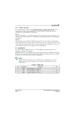
Table 4-5 Lighting Bus
Pin
Connector
Pin Name
I/O
5
J2402
LIGHTING BUS 14V LO/28V LO
--
6
J2402
LIGHTING BUS 14V HI/28V LO
IN
7
J2402
LIGHTING BUS 14V HI/28V HI
IN


