background image

Mounting the Stereo

NOTICE

Do not use the stereo as a template when drilling the mounting holes because this may damage the display and 
void the warranty. You must only use the included template to correctly drill the mounting holes.
Be careful when cutting the hole to mount the stereo. There is only a small amount of clearance between the 
case and the mounting holes, and cutting the hole too large could compromise the stability of the stereo after it 
is mounted.
Be careful when installing the stereo in an aluminum boat or a boat with a conductive hull, if you require the 
electrical system to be isolated from the boat hull.
Do not apply grease or lubricant to the screws when fastening the stereo to the mounting surface. Grease or 
other lubricants can cause damage to the stereo housing.

Before you can mount the stereo in a new location on the mounting surface, you must select a location in 
accordance with the mounting considerations.
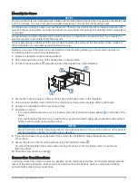
Adhere the template to the mounting surface.
Drill a hole inside the corner of the dashed line on the template.
Cut the mounting surface   along the inside of the dashed line on the template.

Ensure the mounting holes on the stereo line up with the pilot holes on the template.
Using an appropriately sized drill bit for the mounting surface and screw type, drill the pilot holes.
Remove the template from the mounting surface.
Complete an action:

• If you are installing the stereo in a dry location, place the included mounting gasket   on the back of the 

stereo.

• If you are installing the stereo in a location that is exposed to water, apply silicone-based marine sealant 

on the mounting surface around the cutout.

NOTICE

Do not install the included mounting gasket if you applied sealant to the mounting surface. Using sealant 

and the mounting gasket may reduce water resistance.

If you will not have access to the back of the stereo after installation, make the necessary wiring 

connections.

Secure the stereo to the mounting surface using the included screws  .

You should hand-tighten the screws when securing the stereo to the mounting surface to avoid over 
tightening them.

10 Snap the screw covers in place  .

Connection Considerations

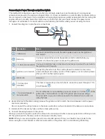
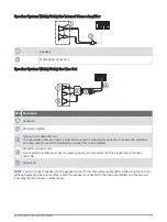
You must connect the stereo to power, to speakers, and to media input sources. You should carefully plan the 
layout of the stereo, speakers, input sources, and optional Fusion PartyBus

 devices and Fusion PartyBus 

network before making any connections.

Apollo SRX400 Installation Instructions

3

Содержание Fusion Apollo SRX400

Страница 1: ...ing or sanding NOTICE When drilling or cutting always check what is on the opposite side of the surface to avoid damaging the vessel Do not use the stereo as a template when drilling the mounting hole...

Страница 2: ...reo in a location that may be exposed to water add a drip loop to the cable to allow water to drip off of the cable and avoid damage to the stereo If you need to mount the stereo outside a boat you mu...

Страница 3: ...4 Ensure the mounting holes on the stereo line up with the pilot holes on the template 5 Using an appropriately sized drill bit for the mounting surface and screw type drill the pilot holes 6 Remove t...

Страница 4: ...a If you are installing the stereo on a boat with a metal hull you must use a ground dependent antenna If you are installing the stereo on a boat with a non metal hull you must use a ground independen...

Страница 5: ...rectly Dim Orange Connects to the boat s illumination wire to dim the stereo screen when the boat s lights are on The gauge of the illumination wire must be suitable for the fuse supplying the circuit...

Страница 6: ...d off automatically when you turn the vessel on and off or when you activate the switch Using this wire to turn the stereo on and off behaves in the same way as using the power button on the stereo to...

Страница 7: ...nly if a circuit breaker is not available or if it provides a more convenient method of cutting power to the stereo Black wire Ground 15 A fuse not included This fuse is required if you are not able t...

Страница 8: ...nter a low power standby mode when you turn off the engines so it can start up faster when you turn on the engines again Black wire Ground 15 A fuse not included This fuse is required if you are not a...

Страница 9: ...ay need to use an RCA splitter to connect this to an amplifier Amplifier on signal wire A connected amplifier must use the same ground as the stereo for this signal wire to function correctly Subwoofe...

Страница 10: ...Fusion PartyBus stereos on a network wirelessly Wired Networking Considerations When you are planning your network installation observe the following considerations for all wired connections You must...

Страница 11: ...on the network it should be configured to be the DHCP server by default See your wireless router instructions for more information If you are not using a wireless router you can configure this device...

Страница 12: ...the Fusion Link app Wireless Network Example with a Wired Switch or Router Fusion PartyBus stereo Wired network switch or wired network router Fusion PartyBus zone stereo or remote control Fusion Par...

Страница 13: ...er or Access Point Fusion PartyBus stereo Wireless network router or wireless access point Fusion PartyBus zone stereo or remote control Fusion PartyBus zone stereo Smartphone using the Fusion Link ap...

Страница 14: ...sary Setting the Fusion PartyBus Device as a Wireless Access Point page 15 Configuring a stereo as a wireless access point makes that stereo the DHCP server and all of the other stereos on the network...

Страница 15: ...ork performance For more detailed configuration instructions see the owner s manual 1 Select SETTINGS NETWORK WI FI ACCESS POINT 2 Select USE DEFAULTS and wait for the device to save the network setti...

Страница 16: ...ing an Ethernet cable You may experience wireless interference if there are many nearby wireless access points Change the channel on your router or wireless access point to test for and correct interf...

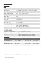
Страница 17: ...h 2 4 GHz 10 dBm nominal Compass safe distance 10 cm 3 9 in On board Class D Amplifier Output music power per channel 70 W max x 2 at 2 ohm per channel Total output peak power 140 W max Output power p...

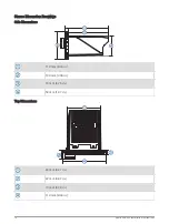
Страница 18: ...Dimension Drawings Side Dimensions 110 mm 4 33 in 100 mm 3 94 in 70 mm 2 76 in 50 mm 1 97 in Top Dimensions 83 mm 3 27 in 22 mm 0 87 in 10 mm 0 39 in 110 mm 4 33 in 18 Apollo SRX400 Installation Instr...

Страница 19: ...Software Updates Go to support garmin com to find software updates and information for your device 68 02 2642 8999 02 2642 9199 Apollo SRX400 Installation Instructions 19...

Страница 20: ...2018 2021 Garmin Ltd or its subsidiaries support garmin com...

Отзывы: