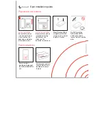
corners of the trim caps , slide the pry tool to the center ,
and remove the trim caps.
8
Ensure the mounting holes on the device line up with the pilot
holes on the template.
9
If the mounting holes on the device do not line up with the
pilot holes on the template, mark the new pilot-hole locations
on your template.
10
Using a 3 mm (
1
/
8
in.) drill bit, drill the pilot holes.
11
Remove the template from the mounting surface.
12
Place the device in the cradle .
NOTE:
You must use the cradle and locking bracket or
locking rings when you flush-mount the device.
13
If you will not have access to the back of the device after you
mount it, connect all necessary cables to the cradle and
secure the cables with the locking bracket or locking rings
before placing the device into the cutout (
).
14
To prevent corrosion of the metal contacts, cover unused
connectors with weather caps (ECHOMAP UHD 7x/9x
models only).
15
Install the rubber gasket pieces on the back of the device.
The pieces of the rubber gasket have adhesive on the back.
Make sure you remove the protective liner before installing
them on the device.
16
Connect each cable to a port on the cradle, using the locking
bracket or locking rings to secure the cables to the cradle
(
).
17
Place the device and cradle into the cutout.
18
Secure the device to the mounting surface using the included
screws .
19
Install the trim caps by snapping them in place around the
edges of the device.
Connection Considerations
After connecting the cables to the cradle, tighten the locking
rings to secure each cable.
Connecting the Cables to the ECHOMAP UHD 6x
Cradle
The connectors on the cables are keyed to fit only in the correct
ports on the ECHOMAP UHD 6x cradle. The connected cables
are held in place by a locking bracket.
1
Slide the cable locking bracket up from the bottom, and
remove the bracket from the cradle.
2
Compare the divots on each cable connector to the keying
on each port to determine which cable corresponds to each
port.
3
Fully and firmly insert each cable through a hole in the cradle,
and securely connect each cable to a port.
NOTE:
If the cables are not inserted far enough into the
cradle, the connectors may not connect securely to the ports,
and the device may appear to lose power or sonar or may
stop working.
4
Place the locking bracket over the cables, and slide the
bracket down to lock the cables in place.
There is an audible click when the locking bracket is installed
correctly.
Connecting the Cables to the ECHOMAP UHD 7x/9x
Cradle
The cables connectors fit only in the correct ports on the
ECHOMAP UHD 7x/9x cradle. The connected cables are held in
place by locking rings.
1
Insert each cable into the appropriate port in the cradle.
2
Spin the locking ring clockwise to lock the cable to the cradle.
Power and Data Cable
• The wiring harness connects the device to power and NMEA
0183 devices. 6-inch devices can also use these wires to
share user data, such as waypoints and routes.
• If you are not connecting NMEA 0183 devices or another
chartplotter to share data, disregard the blue and brown
wires.
• The device has one internal NMEA 0183 port that is used to
connect to NMEA 0183 compliant devices.
• If it is necessary to extend the power and ground wires, you
must use 0.82 mm
2
(18 AWG) or larger wire.
• If it is necessary to extend the NMEA 0183 or alarm wires,
you must use .33 mm
2
(22 AWG) wire.
Item
Wire Function
Wire Color
NMEA 0183 internal port Rx (in)
Brown
NMEA 0183 internal port Tx (out)
Blue
Ground (power and NMEA 0183)
Black
Power
Red
Connecting to Power
WARNING
When connecting the power cable, do not remove the in-line
fuse holder. To prevent the possibility of injury or product
3


