Garmin G5 Electronic Flight Instrument Part 23 AML STC Installation Manual
190-01112-10
Rev. 21
Page 33
•
Make sure there is ample space for the wire harness and mating connectors.
•
Avoid sharp bends.
3.4.5.1 Pressurized Aircraft Considerations
In pressurized aircraft, wiring that penetrates the pressure vessel must be installed in accordance with the
Type Design of the aircraft. Any wires that penetrate the pressure bulkhead must use existing provisions
such as spare pins in the existing bulkhead connectors, or existing sealed wire thoroughfares in
accordance with the AMM. Substantiation for additional holes in the pressure vessel is beyond the scope
of this manual and would require additional data from the aircraft manufacturer or other FAA approved
data.
3.4.5.2 CAN Bus
The primary digital interface used to exchange data between the G5 Electronic Flight Instrument, GMU
11, GAD 29/29B, and GAD 13 is the Controller Area Network, also known as the CAN bus. CAN was
developed by Bosch GmbH in the 1980s, and its specifications are currently governed by ISO 11898-2.
CAN is widely used in aviation, automotive, and industrial applications due to its simplicity and
reliability.
3.4.5.2.1 CAN Bus Architecture
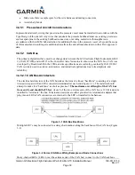
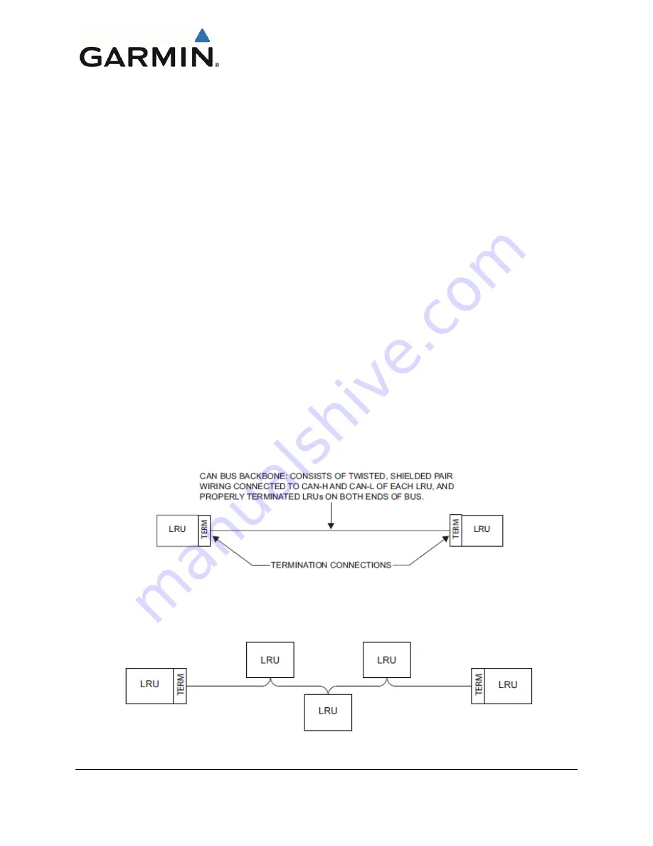
The electrical architecture of the CAN bus takes the form of a linear “backbone” consisting of a single
twisted wire pair with an LRU connected (terminated) at each end (Figure 3-1). The installer should
attempt to make this “backbone” as short as practical.
The maximum overall length of the CAN bus
from end to end should be 85 feet.
At each of the two extreme ends of the CAN bus, a 120 Ω resistor is
installed to “terminate” the bus. Termination resistors are either provided via termination adapters that
plug into an LRUs CAN connection, are internal to the LRU or installed in the harness.
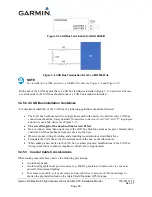
Figure 3-1 CAN Bus Backbone
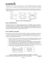
Multiple LRU’s may be connected in a daisy chain manner along the backbone of the CAN bus (Figure
3-2).
Figure 3-2 Correct CAN Bus Wiring Example and Node Connections
Daisy-chained LRUs (LRUs not at the extreme ends of the CAN bus) connect to the CAN backbone

