background image


500W Series 

190-01226-03 Rev. 5 

Instructions for Continued Airworthiness Bell 206B 

Page 21 of 23 

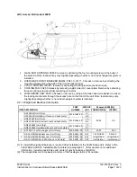
2.7.2  GA 35 GPS, GA 36 GPS, and GA 37 GPS/XM Antennas 

2.7.2.1 Removal 

1. Remove the screws from the outside of the rotorcraft.  

2. Remove old sealant.  

3. Lift the antenna off the rotorcraft and detach the coax (from the outside). If a GA 37 antenna 

verify coax(s) are properly labeled with correct color band. Note: GPS coax is labeled with a blue 
band and XM cable with a yellow band. 

2.7.2.2 Installation 

For GA 35, GA 36, or GA 37 GPS antenna installation, follow the installation procedures contained in the 
installation drawing listed in paragraph 2.1 of this document. 

2.7.2.3  Return to Service 

After removing and reinstalling the GPS antenna, verify the 500W Series unit power-up self-test 
sequence is successfully completed and no failure messages are annunciated. If the unit is unable to 
acquire satellites, move the rotorcraft away from obstructions which might be shading GPS reception.  If 
the situation does not improve, check the GPS antenna installation. 

2.7.3 Cooling Fan 

2.7.3.1 Removal 

1. Extract the screws from the copilot side (LH side) center console cover plate. 

2. Remove copilot side (LH side) center console cover plate. 

3. Disconnect cooling fan electrical connector located under cooling ports on fan. 

4. Extract the three (3X) cooling fan mounting screws to remove cooling fan. 

2.7.3.2 Installation 

1. Install cooling fan using removed hardware. 

2. Reconnect electrical connector to cooling fan. 

3. Reinstall center console cover plate using removed hardware, verifying silicone sponge foam 

used to seal cooling fan intake remains in place on center console cover plate and properly 
seals the fan intake to the louver installed on the center console cover plate. 

2.7.3.3  Return to Service 

After removing and reinstalling the cooling fan verify proper operation of the cooling fan. Apply power to 
the avionics, verify the cooling fan is operating and the FAN FAIL light on the annunciator panel is not 
illuminated. 


2.8 Diagrams 

Rotorcraft specific LRU locations and wire routing diagrams are contained in the 400W/500W Series 
Installation drawing Bell 206B, listed in Section 2.1 of this document. Point to point wiring diagrams are 
in the Appendix of the 500W Rotorcraft STC Installation Manual. Refer to the GNS 500W Series Post-
Installation Checkout Log retained in the rotorcraft permanent records for a list of the interfaced 
equipment and port configurations. 

Содержание 500W Series

Страница 1: ...2 USA Record of Revision Rev Date Description of Change 1 07 16 10 Initial Release 2 08 11 10 Updated ref doc revisions in section 2 1 revised part number and weight of item 2 in table 2 2 1 3 04 09 1...

Страница 2: ...ations contained herein are the property of Garmin International or its subsidiaries and may not be reproduced or used in whole or in part as the basis for manufacture or sale of products without writ...

Страница 3: ...l Operating Information 8 2 4 Servicing Information 8 2 5 Periodic Maintenance Instructions 8 2 6 Troubleshooting Information 11 2 7 Removal and Installation Information 20 2 8 Diagrams 21 2 9 Special...

Страница 4: ...trolled in accordance with the Garmin document control system When this document is revised refer to Section 2 15 for information on how to gain FAA acceptance or approval and how to notify customers...

Страница 5: ...tallation of a 500W series GPS WAAS Nav Com unit under the Garmin Bell 400W 500W HTAWS STC SR02080SE Definition of Abbreviations See Section 1 5 Precautions None Units of measurement None Referenced p...

Страница 6: ...nnunciator panel Installation of optional remote HTAWS annunciators and optional cyclic stick switches for remote control of COM and HTAWS functions are also covered under this STC The 500W Series uni...

Страница 7: ...g whether or not a dual navigator system is installed 2 2 1 Weight and Balance Information ITEM DESCRIPTION PART NUMBER WEIGHT LB Moment ARM IN LONGITUDINAL LATERAL 1 GPS 500W Unit Only 011 01062 XX 5...

Страница 8: ...n application of power to the units and built in test is continuously executed Detected errors are indicated on the equipment via failure annunciations Maintenance of the components installed by this...

Страница 9: ...milliohms Reinstall the 500W Series unit in the mounting rack GPS Antennas Only if antenna is installed by this STC Every 2000 flight hours or ten 10 years whichever is first Perform an electrical bon...

Страница 10: ...of 20 000 hours This life may be more or less than the rated time depending on the operating conditions of the 500W Series unit Over time the backlight lamp may dim and the display may not perform as...

Страница 11: ...m sources of interference The GPS signal levels are very low Improper antenna installation or coax routing Check GPS antenna installation connections and cable routing The GPS antenna must be mounted...

Страница 12: ...S CDI page Wiring connections are incorrect Check wiring ARINC 429 device is not receiving data from the 500W 530W 500W Series unit ARINC 429 output not configured correctly Check ARINC 429 output por...

Страница 13: ...able The ADS B traffic system is reporting that the CSA application has failed Traffic alerting on ADS B traffic is unavailable Ensure the aircraft has a clear view of the sky If problem persists cont...

Страница 14: ...y still operate regardless of the displayed frequency COM needs service 530W only The unit has detected a failure in its communications transceiver The COM transceiver may still be usable Contact Garm...

Страница 15: ...must not be used for actual navigation Check that the DEMO MODE SELECT pin P5001 Pin 75 is not connected G S has failed 530W only The unit has detected a failure in its glideslope receiver Contact Gar...

Страница 16: ...chnical support GTN transfer canceled version mismatch The protocol version or database version don t match between the GTN and GNS units Load the most current cycles of the navigation database to eac...

Страница 17: ...support NRST key stuck GPS 500 only The NRST key is stuck in the enabled or pressed state Try pressing the NRST key again to cycle its operation If problem persists contact Garmin technical support OB...

Страница 18: ...rted by the hardware Reconfigure the unit TERRAIN configuration has changed The unit s terrain settings have changed since it was last turned on in normal mode Reconfigure TERRAIN settings Contact Gar...

Страница 19: ...transfer key is stuck 530W only The remote VLOC transfer switch is stuck in the enabled or pressed state Try pressing the switch again to cycle its operation Contact Garmin technical support VLOC tra...

Страница 20: ...bezel until the unit is firmly seated in the rack NOTE The installation configuration and user settings are stored internally in the 500W Series unit and will be lost when the 500W Series is replaced...

Страница 21: ...LH side center console cover plate 2 Remove copilot side LH side center console cover plate 3 Disconnect cooling fan electrical connector located under cooling ports on fan 4 Extract the three 3X cool...

Страница 22: ...n Drawing FASTENER TYPE AND TORQUE 6 32 Screw 4 2 inch pounds 6 32 Screw 12 15 inch pounds 8 32 Screw 12 15 inch pounds 10 32 Screw 12 15 inch pounds 10 32 Screw 20 25 inch pounds 500W Unit Mounting R...

Страница 23: ......

Отзывы: