background image


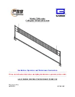
7200 Collegiate Volleyball System


Introduction


Thank you for your purchase of a model 7200 Collegiate Volleyball System.  To ensure that our 
equipment will provide years of use to you, we are including this installation, operation, and 
maintenance guide.  This guide will provide information on the proper assembly and installation 
methods, operating procedures, and preventative maintenance of your portable backstop. 
 
Please note that a Bill of Materials is being included with this guide.  Please check that all of the 
parts called out on the Bill of Materials are present prior to beginning assembly and setup.  
Please do not substitute for factory parts.  Please contact the PSS or Gared Sports customer 
service department and allow them to determine if substitute parts are acceptable. 
 
It is recommended that an individual who has been properly trained perform assembly and set up 
of the backstop.  No one under the age of 18 should attempt assembly or set up of the unit, unless 
properly supervised. 
 
To prevent normal wear and tear from shortening the life of the unit, preventative maintenance 
inspections and repairs should be performed at least once per year.  If the units are subject to 
high or unusual usage, inspections should be scheduled to occur more frequently.  If items are 
found to be nonconforming, replacements can be ordered from an authorized dealer.  When 
contacting your dealer, please have information regarding the name of the project and any 
applicable warranty information. 


7200 SERIES PARTS LIST 

MODEL 

7200  7205  7202  7207  7203  7208 

ITEM 

PART 

NUMBER 

DESCRIPTION 

1 CT 

1 CT 

2 CT 

2 CT 

3 CT 

3 CT 

7216 

WINCH POST, 7200 

7210 

END POST, 7200 

7226 

CENTER POST W/WINCH, 7200 

‐ 

‐ 

6405 

FLOOR SLEEVE, 4" INSIDE DIA. 

‐ 

‐ 

‐ 

6430 

6" BRASS FLOOR COVER ‐ LOW PROFILE  

‐ 

‐ 

‐ 

6010 

UPRIGHT PAD ‐ CUSTOM COLOR  

6020 

CTR UPRIGHT PAD ‐ CUSTOM COLOR 

‐ 

‐ 

601651165 

VOLLEYBALL NET 

1028‐22‐00 

NET ANTENNA 

10 

7607‐22‐00 

NET SIDELINE MARKER     

11 

6251 

BUCKLE COVERS SET OF (6) 

12 

7608 

NET HEIGHT CHECKER     

13 

601751793 

MANUAL, 7200 VOLLEYBALL SYSTEM 


Posts are shipped fully assembled.  Verify all parts listed on packing list are present prior to 
installation. 

Содержание 7200 Series

Страница 1: ...lleyball System Installation Operation and Maintenance Instructions Please read all instructions before attempting installation or operation of these units SAVE THESE INSTRUCTIONS FOR FUTURE USE PUBLI...

Страница 2: ...em 1 Table of Contents Section Page No Introduction 2 Parts List by Sub Assembly 2 3 Specifications 4 5 Floor Sleeve Installation 6 7 Floor Cover Installation 8 Post and Net Installation Instructions...

Страница 3: ...from shortening the life of the unit preventative maintenance inspections and repairs should be performed at least once per year If the units are subject to high or unusual usage inspections should be...

Страница 4: ...4127 DECAL GARED TALL BLACK 12 2 121974128 DECAL G 6000 7200 POST 13 4 234 10 32 8Z SCREW MACH PAN HD PHIL 10 32 UNF X 0 5 14 2 509 5 18 10 HEX SOCKET BUTTON HEAD 5 16 18 X 0 625 15 2 544 5 18 HEX JAM...

Страница 5: ...7200 Collegiate Volleyball System 4 MODEL 7200 COLLEGIATE VB SYSTEM MODEL 7205 COLLEGIATE VB SYSTEM less SLEEVES AND COVERS...

Страница 6: ...7200 Collegiate Volleyball System 5 MODEL 7202 COLLEGIATE TWO COURT VB SYS MODEL 7207 COLLEGIATE TWO COURT VB SYS less SLEEVES AND COVERS...

Страница 7: ...debris from falling in or grout from entering the bottom of sleeve 6 Insert the 4 1 4 O D steel sleeve and work it down into the grout until the inside bottom of the sleeve is 14 below the TOP surfac...

Страница 8: ...7200 Collegiate Volleyball System 7 Installation Instructions for Ground Sleeves...

Страница 9: ...7200 Collegiate Volleyball System 8 Counterbore Details and Floor Cover Installation...

Страница 10: ...5 Attach the net cable to the J hook on the end post with Attach the net cable to the winch belt with a snap link 6 Next turn the winch handle clockwise to tighten the net cable Note that the height...

Страница 11: ...to be retightened periodically Expect some initial stretch in the net 9 Minor height adjustments can be made by screwing the foot pads on the bottom of the posts in or out Posts must be removed from t...

Страница 12: ...ll system down a Remove antenna b Unhook net straps from posts at both ends c Crank winch counterclockwise until net cable can be unhooked from snap links d Fold net up and transport net and posts to...

Страница 13: ...bolts or nuts should be tightened 5 Check Sliding components and strap for wear Maintenance Check Sheet Date Unit Anchors Floor Sleeves Anchors bolts OK Repair Replace Floor sleeves covers OK Repair...

Страница 14: ...ed Holdings LLC Performance Sports Systems Gared Sports 9200 E 146th Street 9200 E 146th Street Noblesville IN 46060 Noblesville IN 46060 800 848 8034 800 325 2682 www perfsports com www garedsports c...

Отзывы: