MIS
TP 1
25/E
N1
/07
0
1
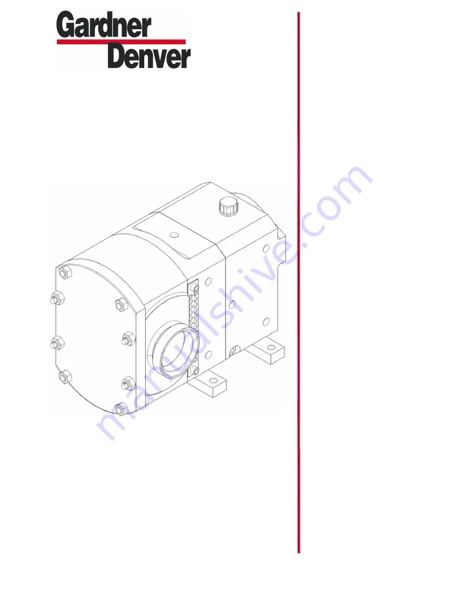
OPERATION, AINTENANCE and INSTALLATION MANUAL and PARTS LIST
ROTARY LOBE PUMP
STP 125
STP125 VERSION: 03
February 3, 2015
Страница 1: ...MIS TP 125 E N1 0701 OPERATION AINTENANCE and INSTALLATION MANUAL and PARTS LIST ROTARY LOBE PUMP STP 125 STP125 VERSION 03 February 3 2015...
Страница 2: ......
Страница 3: ...on 5 3 2 Principle of operation 5 3 3 Pump dimensions 6 3 4 Pump weight 6 3 5 Pump displacement 6 3 6 Pump information chart 6 3 7 Pressure relief valve 6 4 0 SystemDesignandInstallation 4 1 System de...
Страница 4: ...he timing gears 16 8 11 Shaft and bearing removal 16 9 0 Assembly 9 1 Fitting shafts into the bearing housing 17 9 2 Fitting the front seal retainers 17 9 3 Fitting timing gears and setting rotor timi...
Страница 5: ...ating tank 12 1 Heatingtankremoval 23 12 2 Heatingtankfitting 23 13 0 Relief valve 13 1 Disassembly reliefvalve 24 13 2 Assembly reliefvalve 24 14 0 Faults causes and remedies 25 15 0 Torque settings...
Страница 6: ...he materials of construction and product seals are compatible with the pumping application and that adequate NPSH is available For specific guidelines contact your supplier quoting pump serial number...
Страница 7: ...rstart inthe wrongdirection of rotation with liquid in the pump Never put your hands or fingers inside the port connections Operation Always observe the technical data Nevertouchthepumporthepipelines...
Страница 8: ...Wash with soap and water Eyes Flushwithwater seekmedical attention In all cases if symptoms persist seek medical attention Material Use Majorhazard SILICONE SEALANT GEARBOX SEAL RETAINERS GENERAL SEA...
Страница 9: ...enable the pump to be lifted either with or without the hydraulic drive fitted Alternatively slings should be wrapped around the ports and the hydraulic drive flange Note To stop the slings slipping a...
Страница 10: ...otors The direction of flow is reversed by changing the direction of rotation of the pump s drive shaft The pumping principle is as follows The volume at the inlet increases when the rotors rotate and...
Страница 11: ...gall 3 6Pumpinformationchart 3 7Pressure relief valve A integral relief valve is available It can be used regardless of the direction of rotation A manual override is also available The relief valve i...
Страница 12: ...common dischargelines Do Make the necessary piping arrangements if steam is required for heating cooling tanks Plan View SuctionLine Do not Subject the pump to rapid temperature changes during C I P C...
Страница 13: ...Use long radius bends wherever possible Provide Valves on each side of the pump to isolate the pump whennecessary Keep Pipework horizontal where applicable to reduce air locks Include eccentric reduce...
Страница 14: ...its effectiveness If this cap is lost at any time it is important that a replacement of the same type is fitted immediately 5 1Lubricatingthepump The gearbox should be filled to the mid point of the s...
Страница 15: ...ump connections and pipework joints tight and leak free 4 Is there lubrication in the pump and drive unit 5 Are the pipework valves open 6 Are all safety guards in place 7 Start then stop the pump to...
Страница 16: ...te the pump drive from all power and control supplies 3 Close the pipework valves to isolate the pump 4 Ensure allauxiliaryservices such as heating cooling tanks supply etc are isolated 5 If the pump...
Страница 17: ...ward on the proportional controlvalveandslowlyincrease by pushing the handle tofull pump speed Whendrivenelectricallystartthe systemand slowly increasethe speed withthehandwheelonthebeltvariator Using...
Страница 18: ...the seal continues to leak at pressures below 145 psi it is an indication that the primarysealmaybe permanently damaged and should therefore be replacedattheearliestopportunity Checking the oil seals...
Страница 19: ...anynoxious hazardous products havebeenpumped Isolate pump drive unit from all power and control supplies Close pipework valves to isolate the pump Disconnect the pump from the drive unit Secure The pu...
Страница 20: ...nsert a plastic block between the two rotors 13 to stop them turning 2 Using a spanner remove the rotor nuts 9 These nuts have right hand threads 3 Therotorscan beremovedfromtheshafts 28 29 by hand or...
Страница 21: ...andpress outtheoilseal 41 Itis essential to renew the oilseal upon re assembly 4 Remove the gasket 17 8 10 Removing the timing gears 1 Pull the rear inner bearing races 39 off the shafts A puller or e...
Страница 22: ...haft lightly tap each end of the shaft with a soft malletandrotate Check the torque required to turn the shaft in the bearings The bearings are correctly adjusted when the torque to turn each shaft is...
Страница 23: ...rence by adding or removing shims 30 between the gear face andshaftshoulderasindicatedinthe diagram Fullytighten the gear retaining nuts and check the clearances are within the specification limits If...
Страница 24: ...eeve 9 Fitthesleeves ontotheshafts ensuringthat the drive pins locate in any other position than themissingspline 10 Fitthesealsleeveretainingclips 64 onto theshafts 11 Fit the rotorcase 11 and retain...
Страница 25: ...the O ring 10 3 To remove the seal housing 1 Remove the gland guards 21 2 Thoroughly clean the inside and outside of the seal area on the rotorcase and the bores of the rotor 3 Remove theproduct O rin...
Страница 26: ...ng Seal Face Static Seal Face Rotary Wave Spring 11 2 Single mechanical seal removal 1 Remove the gland guards 21 2 Thoroughly clean the inside and outside of the seal area on the rotorcase and the bo...
Страница 27: ...engage correctly 5 Press therotating faces 83 intotherotor bores ensuring the drive pins locate correctly 6 Position the seal housing loosely in the rotorcase with the flat inside the rotor casealigne...
Страница 28: ...ation a hydrostatic test of the heating system is recommended Hydrostatic test pressure water 90 psi Maximum working pressure 55 psi Heating tanks should be in operation approximately 15 minutes prior...
Страница 29: ...l in the system ensure there is no pressure in the pump head 2 Clean the outside of the pump and valve casing 3 Remove the nuts 60 and housing 54 Loosen the nuts equally in order to move the housing a...
Страница 30: ...14 Faults causes and remedies...
Страница 31: ...ended torque settings in lbft Description Pump ToolSizes STP125 Frontcovernut 30 19mm Rotorcaseretainer 30 16mm Rotornut 110 41mm Bearinghousingscrew 33 8mm Allen Relief valve nut 15 14mm Footscrew 75...
Страница 32: ...STP125 Pump Model Exploded View Drawing 16 Exploded view drawing and parts list 41 i i i i i i i i i i i 1 STP125 Page 30...
Страница 33: ...ARD GLAND FP2000 STP125 2 521143202 22 SOCKET HD CAPSCREW M8x16mm 316 STAINLS 4 126008216 23 TIMING GEAR SET FP2000 STP125 1 529000208 24 TIMING GEAR SET FP2000 STP125 1 529000208 28 SHAFT DRIVEN STP1...
Страница 34: ...G STP125 2 518081209 42 SEAL SLEEVE O RING VERSION STP125 2 516041214 43 O RING ROTOR STP125 NBR Viton PTFE 2 522001246 522011242 522031207 45 O RING SHAFT STP125 NBR Viton PTFE 2 522001247 522011243...
Страница 35: ...BR Viton PTFE 2 522001250 522011241 522031206 45 O RING SHAFT STP125 NBR Viton PTFE 2 522001247 522011243 522031208 64 CLIP SHAFT SLEEVE RETAINER STP125 2 518081203 65 O RING HOUSING STP125 NBR Viton...
Страница 36: ...MP 65 PSI RELIEF VALVE 1 517022201 57 ANCHOR PLATE SS FOR RELIEF VLV STP125 1 532120201 58 SEAL DIAPHRAGM FP2000 STP125 PTFE NBR PTFE Viton 1 513132200 513132201 59 STUD M10 1 5 x 40MM LG S S STP125 4...
Страница 37: ...SKT HD ISO 8 8 M12 x 30mm PLTD 4 130112030 68 KEY RND END 10MM X 8MM X 63MM 1 199050209 69 SHAFT DRIVE KEYED STP125 1 504033216 72 HEATING TANK FOR ROTORCASE SS STP125 2 500030210 73 CAPSCREW SKT HD M...
Страница 38: ...TING RING STP125 2 518081209 42 SEAL SLEEVE LIP SEAL VERSION STP125 2 516041215 43 O RING ROTOR STP125 NBR Viton PTFE 2 522001246 522011242 522031207 45 O RING SHAFT STP125 NBR Viton PTFE 2 522001247...
Страница 39: ......
Страница 40: ...For additional information contact your local representative or visit www contactgd com compressors 2015 Gardner Denver Inc Printed in U S A...