background image

Part III: Install the MyLifter Units

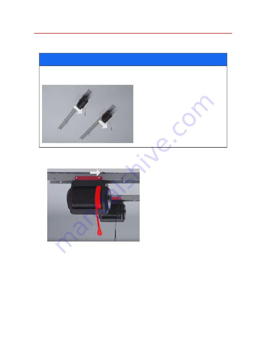
Installing the MyLifter units on two different tracks

NOTICE

If your studs run 

parallel

 to your garage door, you will need to install both MyLifter units 

facing in the same direction with each on its own Smart Track.

 1.  Install each lifter on the Smart Track by aligning each cable with one of the pul-

ley marks, using the four Long Quick Release Pins.

Make sure the pins go all the way through the holes in the MyLifter brackets and 
the Smart Track.

 2.  Place the carabiners in the fifth hole on the same side of the Smart Track as the 

cable coming out of the lifters.

Содержание Hard Top Lifter

Страница 1: ...Installation and Operation Guide ...

Страница 2: ...8 Installing the MyLifter units on the same Smart Track 19 Installing the power adapter 20 Part IV Attach the MyLifter Cables to the Hard Top Lifter Frame 23 Pair the MyLifter units with your smart device 23 Create a locked group 24 Attach the Hard Top Lifter Frame to your hard top 25 Attach the cargo net 26 Part V Lift Your Hard Top 27 Using the MyLifter App 28 Pair Your MyLifter With The App 29 ...

Страница 3: ...To create a Flex Group 34 ...

Страница 4: ...anship from personal normal household use in accordance with the Owner s Manual Warranty Does Not Cover This warranty does not cover installation commercial use defects resulting from accidents damage while in transit to our service location or dam age resulting from altercations misuses or abuse lack of proper maintenance unau thorized repair or modifications of the product affixing of any attach...

Страница 5: ... NOT EXPRESSLY SET FORTH HEREIN WHETHER EXPRESS OR IMPLIED INCLUDING BUT NOT LIMITED TO ANY WARRANTIES OF MERCHANT ABILITY AND FINESS FOR A PARTICULAR PURPOSE Limitation of Liability THE SOLE REMEDIES AFFORDED UNDER THIS WARRANTYARE REPAIR REPLACEMENT OR IF REPAIR OR REPLACEMENT IS NOT COMMERCIALLY PRACTICABLE OR CANNOT BE TIMELY MADE A REFUND OF THE PURCHASE PRICE IN NO EVENT SHALL THE LIABILITY ...

Страница 6: ...adiate radio frequency energy and if not installed and used in accordance with the instructions may cause harmful inter ference to radio communications However there is no guarantee that interference will not occur in a particular installation If this equipment does cause harmful interference to radio or television reception which can be determined by turning the equipment off and on the user is e...

Страница 7: ...operation instructions l Do not lift the Hard Top Lifter while hands or other body parts are near the system l Do not stand under the Hard Top Lifter l Do not use the Hard Top Lifter to lift people or animals l Do not use the Hard Top Lifter to lift or lower items over people or animals l Total lifting capacity for Hard Top Lifter is 175 lbs l Always balance load before lifting If your MyLifter ca...

Страница 8: ...rack System 3 Install the MyLifter Units 4 Attach the MyLifter Cables to the Hard Top Lifter Frame 5 Lift Your Hard Top What you need Installation requires the following tools l A ladder l Stud finder l Tape measure l Pencil l A drill l 13 mm wrench or socket wrench Identify parts Inspect the box and make sure that you have all the parts shown in the image below ...

Страница 9: ...If you are missing parts contact Garage Smart for replacements visit https gar agesmart com or call 833 234 8711 6 00 am to 10 pm Mountain Time ...

Страница 10: ... 1 Insert the Narrow Length Adjuster A into the Wide Length Adjuster B with the rectangular slot at opposite ends l For a 4 door JL hard top extend the length of the assembly so that 7 holes of part A are exposed from part B l For a 2 door hard top extend the length of the assembly so that 13 holes of part A are exposed from part B l For a 4 door JK hard top extend the length of the assembly so th...

Страница 11: ...o the first and last overlapping holes Where part A extends out of part B will become the rear of the lifting frame 3 Repeat steps 1 and 2 to put together the second Length Adjuster Assembly 4 Insert the Wide Width Adjusters C through the rectangular slots at the front and rear of each Length Adjuster Assembly with the open end facing up 5 Align each hole in part C with the center of each Length A...

Страница 12: ...6 On the rear of the assembly slide part D into part C 7 For the JL or JK model hard top align the 1st hole of part D with the hole in part C ...

Страница 13: ...e the Rear Support Adjuster 10 On the front of the assembly slide part E into part C 11 For the JL or JK model align the first hole of part E with the hole in part C NOTICE Other hard top models will need custom installation 12 Place the quarter inch quick release pin through the aligned holes 13 Repeat steps 10 to 12 on the opposite side of the front of the assembly to com plete the Front Support...

Страница 14: ...14 Slide the foam blocks over the Front Support Adjuster and the Rear Support Adjuster and position them against part C ...

Страница 15: ...me Assembly NOTICE The Pulley Frame placement will vary based on your hard top length and what you place in the cargo net l For a 4 Door JL hard top the back of your Pulley Frame should be positioned 15 holes from the Rear Support Adjuster l For a 2 Door JL hard top the back of your Pulley Frame should be positioned 8 holes from the Rear Support Adjuster ...

Страница 16: ...ur Pulley Frame should be positioned 8 holes from the Rear Support Adjuster NOTICE Other hard top models will need custom installation 17 After placing your Pulley Frames in the correct position for your hard top secure them with four 10 mm quick release pins on the first and last overlapping holes The Hard Top Lifting Frame should now be completely assembled ...

Страница 17: ... Pulley Frame that is closest to the back and side walls We recommend that the distance to the back wall be at least five feet so you can open your tailgate for hard top removal We recommend that the distance to the nearest side wall be at least four feet so you can open your doors 3 Make the same measurements on the ceiling and mark where the back of the Pulley Frame closest to the back and side ...

Страница 18: ...from the mark to the garage door be at least five feet so the top of your garage door and the hard top don t bump into each other when raised 5 From your mark on the ceiling make three more marks that create a perfect 15 inch square 6 Measure from each point to the nearest walls to make sure your square will sit straight ...

Страница 19: ... you install the Smart Tracks 7 Determine which way you need to orient your Smart Tracks There are two dif ferent ways to orient your Smart Tracks a If your ceiling studs run parallel to the garage door the Smart Track pieces will need to be installed perpendicular to the garage door with a MyLifter on each track ...

Страница 20: ...stalled parallel to the garage door with your two MyLifters on the same track 8 Use a stud finder to find the two studs that are nearest to your marks on the ceil ing Depending on your stud orientation one stud may sit between your marks with the other on the outside of your marks Or the studs will sit just outside of both sets of marks ...

Страница 21: ...raw an X to mark the center of the stud This is called the stud center method which ensures that you will drill into the strongest part of the stud making your lifter kit much more secure WARNING If your garage ceiling is textured triple check the center marks you made to ensure that you have found the center of each stud Failure to secure the Smart Tracks to the center of each stud could cause pr...

Страница 22: ...e through the track s holes 12 Double check that each set of marks are 15 inches apart 13 Using the included 6 mm drill bit drill a vertical pilot hole at least three inches into each center mark you made 14 Hold your Smart Track in place over one of the holes you drilled and screw in a lag screw and washer almost all the way so you can still move the Smart Track ...

Страница 23: ... you drilled for the opposite end of the Smart Track and screw in another lag screw and washer all the way Be sure to tighten both lag screws so the Smart Track is flush and secure against the ceiling 16 Repeat steps 12 and 13 to install the second Smart Track piece ...

Страница 24: ...n the same direction with each on its own Smart Track 1 Install each lifter on the Smart Track by aligning each cable with one of the pul ley marks using the four Long Quick Release Pins Make sure the pins go all the way through the holes in the MyLifter brackets and the Smart Track 2 Place the carabiners in the fifth hole on the same side of the Smart Track as the cable coming out of the lifters ...

Страница 25: ...rt Track with the cables facing toward the opposite Smart Track 1 Install each lifter on the Smart Track aligning the cables with the pulley marks and using the four Long Quick Release Pins Make sure the pins go all the way through the holes in the MyLifter brackets and the Smart Track There should be three open holes between the MyLifter units on the Smart Track 2 Place the carabiners on the far ...

Страница 26: ...all the power adapters anywhere on the Smart Track NOTICE The universal mounting bracket attached to the bottom of the power adapters lets you easily slide and snap them into place in any open area on the track Slide the bracket until you feel it snap into the Smart Track holes The universal mounting bracket is removable so you can remove the power adapter from the bracket if you need to ...

Страница 27: ... to 3 to install the other power adapter 5 Locate your nearest power outlet 6 Plug the three pronged cable from the power adapter that is furthest from the out let into the power adapter that is closest to the outlet 7 Plug the closest power adapter into the nearest outlet 8 Secure and organize excess cable lengths a Wrap excess cable length around the power adapter b Or nest the cable inside the ...

Страница 28: ......

Страница 29: ...s screen This screen displays a list of all lifters within range of your Bluetooth com munications If you do not see any available lifters make sure you have plugged in the power cable to the nearest outlet On the MyLifter units you should see a slow blinking yellow Status light 3 Firmly press the Pair button next to the Status light on both lifters When the Status light blinks green the lifters a...

Страница 30: ...r each set of bikes individually Use a Locked Group when multiple lifters are required to lift or lower a single item The Locked Group ensures that all lifters in the group lift and lower items at the same time and at the same speed For example you need to create a Locked Group for the lifters attached to your Hard Top Lifter Frame because the lifters are raising and lower ing a single item that y...

Страница 31: ... 1 Back your vehicle into the garage under the raised Hard Top Lifter Frame 2 Make sure all electrical and physical connections between your hard top and your vehicle are disconnected according to your manufacturer s instructions 3 Disconnect your Freedom Panels and store them in your storage bags accord ing to the manufacturer s instructions 4 On the Device Control screen in the MyLifter app pres...

Страница 32: ...e rear straps to the Rear Support Adjuster 3 Thread the cargo net over the roll bar The cargo net must go over the side roll bars as well 4 Connect the front straps to the Front Support Adjuster 5 Tighten each side of the cargo net 6 Make sure that the straps at each corner connection sit vertically You may need to make frame adjustments to make your straps vertical ...

Страница 33: ...e hard top raised drive your vehicle out of the garage 3 Store your Freedom Panels in the cargo net 4 On the Device Control screen in the MyLifter app tap the Smart Lift button to raise the hard top to the Smart High position With your Smart High and Smart Low points set you can now easily lift and lower your hard top with a simple tap on the appropriate button ...

Страница 34: ...etooth connection Be sure to enable your mobile device s Bluetooth capabilities before attempting to pair with your lifter In this section you will learn how to l Pair your MyLifter app with your MyLifter units l Edit and rename the MyLifter units l Manually operate your lifters l Set your Smart High and Smart Low points l Create Locked and Flex groups ...

Страница 35: ...within range of your Bluetooth com munications If you do not see any available lifters make sure you have plugged in the power cable to the nearest outlet On the MyLifter units you should see a slow blinking yellow Status light 3 Firmly press the Pair button next to the Status light on your lifter When the Status light blinks green the lifters are paired with your app On the Available Lifters scre...

Страница 36: ... upper right hand corner of the screen The button name changes from Edit to Exit and the app enters Edit Mode In Edit Mode you can rename the lifters or delete them if you need to 3 Tap the pencil icon to rename the lifters 4 Type a name for the lifter and then tap OK 5 Tap Exit in the upper right hand corner to close the Edit Mode ...

Страница 37: ...time you can create groups The following graphic gives you an overview of the Device Control screen interface and its manual operation features Set the smart high and low points 1 On the Device Control screen press and hold the Manual Lift button to lift an item to the garage ceiling CAUTION When lifting manually make sure that you leave at least six inches between the item and the lifter Do not r...

Страница 38: ...item to the floor You will want to leave a little bit of slack in the cable to make it easier to remove the item from the lifter frame 5 Tap the Set Low button to set your smart low point An alert is displayed asking Are you sure you want to set the smart low at this position 6 Tap SET to set the smart low position After the smart high and low points are set simply tap the Smart Lift or the Smart ...

Страница 39: ... lifters are required to lift or lower a single item The Locked Group ensures that all lifters in the group lift and lower items at the same time and at the same speed For example the Garage Smart Universal XL HD Lifter requires two MyLifter units to lift large and oddly shaped items In order to keep the load balanced as the item is lifted the two MyLifter units need to be locked together so they ...

Страница 40: ... step 5 until all of the cables on all lifters in the group are at the same position 7 Tap SET REFERENCE to set the current position of all cables as the reference point An alert opens asking Are you sure you want to set the smart lifters as level at this position 8 Tap SET 9 The newly created group is added to the Home screen 10 Tap the name of the group to open it in the Device Control screen 11...

Страница 41: ...ition the names of the lifters you added to the flex group are listed on the Home screen so you can still control them individually 5 Tap the name of the flex group to open it on the Device Control screen 6 Lift and lower the grouped lifters using the controls on the Device Control screen ...

Отзывы: