background image

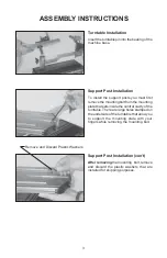
Installing the Tensioner

Remove the button head screw and washer
located at the end of the tensioner bar with
the 3 mm hex wrench provided. Slide the
tensioner onto the bar, being careful to align
the bar with all of the bearings and the drive
gear with the gear track. Replace the screw
and washer into the end of the tensioner bar.

Note: The tensioner bar is equipped with a
tensioner travel stop to limit travel of the
tensioner along the bar.

ASSEMBLY INSTRUCTIONS

Support Post Installation (cont’d)

Place the support post onto the central slot
of the turntable. With your fingers placed
through the large hole in the underside of the
turntable, press the mounting plate against
the inside top surface of the turntable while
aligning the hole in the support post with the
hole in the mounting plate and fix them with
the mounting bolt. Repeat procedure on to
attach the support post on the opposite side
of the turntable.

4

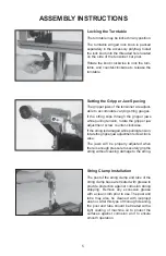
Travel Stop

Tensioner Travel Stop

The tensioner bar is equipped with a tensioner
travel stop to limit travel of the tensioner
along the bar and prevent contact between
the tensioner and the racquet mounting sys-
tem while stringing. The travel stop is lo-
cated about midpoint along the tensioner bar
below the gear track.
To disengage the stop, pull and hold the
knob, rotate 90 degrees and release. To
engage the stop, repeat the above proce-
dure until the travel stop pin protrudes be-
yond the opposite surface of the tensioner
bar.

Содержание X-Stringer

Страница 1: ...OWNER S MANUAL Issue 1 May 2004 Copyright 2004 GAMMA Sports All Rights Reserved X ST STRINGING MACHINE Provided by www gssalliance com...

Страница 2: ...limited to String Clamp adjustment as described on page 13 tension calibration as described on page 11 Tensioner Brake adjustment as described on page 12 and clamp base locking nut adjustment as descr...

Страница 3: ...ll Racquets Without Adapters Parallel Jaw Gripper w Diamond Dust Coated Gripping Surfaces Professional Dual Action Rotating Diamond Dust Coated Fixed String Clamps High Strength Extruded Aluminum Fram...

Страница 4: ...le pin into the bearing of the machine base Support Post Installation To install the support posts you must first remove the mounting bolt from the mounting plate that sets inside the central cavity o...

Страница 5: ...side of the turntable press the mounting plate against the inside top surface of the turntable while aligning the hole in the support post with the hole in the mounting plate and fix them with the mou...

Страница 6: ...in any position The turntable winged lock knob is packed separately in the accessory polybag Install the lock knob into the threaded hole located on the side of the tensioner bar post Rotate the knob...

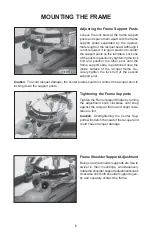
Страница 7: ...bolt of the second support post Caution To avoid racquet damage the center posts should not contact the racquet prior to locking down the support posts Tightening the Frame Supports Tighten the Frame...

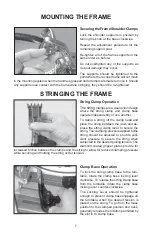
Страница 8: ...urntable rotate the clamp base locking lever counter clockwise The Locking Lever should be tightened enough to prevent clamp base slippage on the turntable when the desired tension is placed on the st...

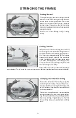
Страница 9: ...d To begin stringing the main strings thread the two ends of the string through the two center holes at the appropriate end of the frame and continue through the opposite center holes Thread one end o...

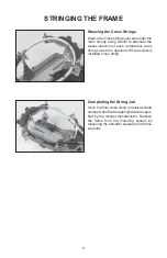
Страница 10: ...ecutive cross string so as to be opposite of the previously installed cross string Completing the String Job Once the final cross string is tensioned and clamped tieoffattheappropriateholespeci fied b...

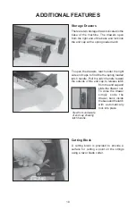
Страница 11: ...awer back inside thebaseandthelatch with automatically lock into place Storage Drawers There are two storage drawers located in the base of the machine The drawers open from the right end of the base...

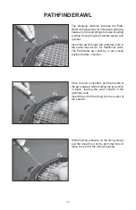
Страница 12: ...essure on the string slowly pull the sheath out of the grommet hole to leave the end of the string exposed The stringing machine includes the Path finder stringing awl which creates a pathway between...

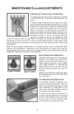
Страница 13: ...string it may be excessively tight and should be adjusted by turning the Adjustment Knob counter clockwise to open the gap between the jaws The clamp jaws should be cleaned periodically to be free fro...

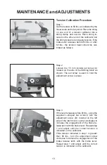
Страница 14: ...he brake lever releases before 60 lbs or after 60 lbs the tension head should be cali brated as follows Step 3 If the lever releases before 60 lbs using the supplied L shaped hex wrench turn the adjus...

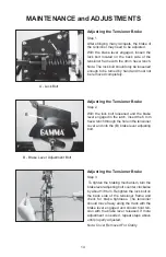
Страница 15: ...lever engaged in the latch insert the 6 mm hex wrench through the hole in the tensioner cover and into the B brake lever adjusting bolt B Brake Lever Adjustment Bolt Adjusting the Tensioner Brake Ste...

Страница 16: ...h such as a toothbrush scrub the inside surfaces until all debris is removed Clean the jaws with isopropyl alcohol and re assemble String Clamp Base Clean the base of the clamps and the top of the tur...

Страница 17: ...16 NOTES...

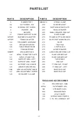
Страница 18: ...OB ARM ADJUSTMENT SCREW SHOULDER V CLAMP PART MDCSC10 259 262 263 265 269 270 271 272 273 274 275 276 277 278 282 283 285 286 287 288 70 MPSA MA 98A 108 109 251 DESCRIPTION STRING CLAMP SLIDE BRACKET...

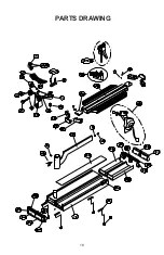
Страница 19: ...18 PARTS DRAWING...

Отзывы: