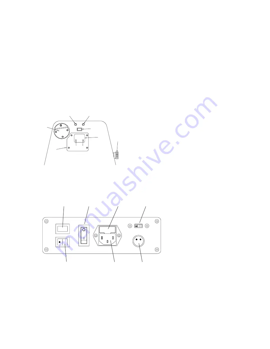
Front Panel Features
“A” - Spilt Drum String Gripper
“B” - Tensioning Button Switch
“C” - Tension Adjustment Knob
“D” - L.E.D. Tension Display
“E” - Red LED
“F” - Green LED
“G” - L.E.D. Display Cover Plate
“H” - High Tension Calibration Port
“L” - Low Tension Calibration Port
7
“A”
“B”
“C”
“D”
“E”
“F”
“G”
“A”
“B”
“C”
“D”
“E”
“F”
“G”
“L” “H”
Side Panel Features
“A” - Lighted On-Off Power Switch
“B” - Power Cord Socket
“C” - Sliding Fuse Holder w/ Spare Fuse
“D” - Gripper Reversing Switch
“E” - 110V / 220V Switch
“F” - 2 Pin Foot Pedal Switch Socket
“G” -Tensioner Speed Switch
Figure 1
Front Panel
Figure 2
Side Panel
Refer to Figures 1 and 2 for power connection and control information.
Before connecting to the power supply, check the voltage supply switch setting
located on the side panel as shown in Figure 2.
To change from 110 volts service to
220 volt service simply slide the switch fully to the right or to the left until “110V” or
“220V” appears on the switch plate.
To install the power cord, simply insert the female end of the power cord into the Power
Cord Socket located on the side panel and plug the male end into a grounded power outlet.
When using extension cords, use grounded heavy duty extension cords rated for 15 AMP
service. To connect the foot pedal switch, insert the 2 pin mail connector located at the end
of the foot pedal switch cord, into the two pin receptacle located in the side panel. Tighten
the connector with the sleeve nut located on the foot pedal switch connector.
Connections & Controls


