24
GWF-7075 Manual —
LS10147-002GF-E:G 10/5/2022
Control Panel Installation
Wiring Specifications
The total worst case current is calculated as follows:
Using this value, and referring to the Wiring Distance table, it can be found that the available options are:
•
370 feet maximum using 22 Gauge wire
•
938 feet maximum using 18 Gauge wire
•
1493 feet maximum using 16 Gauge wire
•
2362 feet maximum using 14 Gauge wire
4.6.3 Wiring Configurations
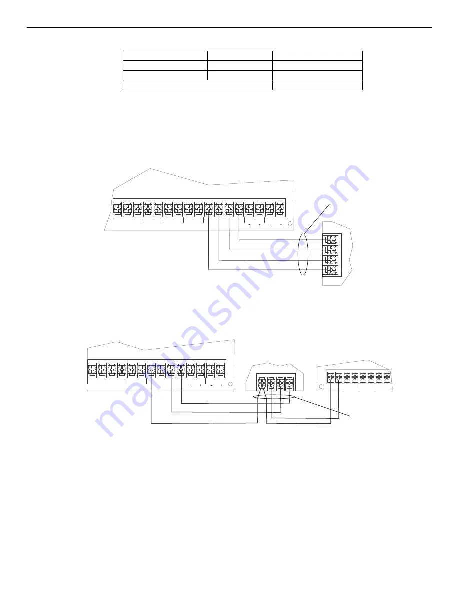
Figure 4.7 illustrates the Class B configuration.
How to Power SBUS Devices From an Auxiliary Power Supply
Figure 4.8 illustrates how to power SBUS devices from an auxiliary power supply such as the GFPS-6S or GFPS-9S, when the maximum
number of SBUS devices exceeds the FACP SBUS power requirements.
Current Draw
= 2 x 0.100 amps
= 0.200 amps
GFPS-6S Current Draw
= 1 x 0.010 amps
= 0.010 amps
5824 Current Draw
= 1 x 0.045 amps
= 0.045 amps
Total Worst Case Current Draw
= 0.255 amps
NO
NC
C
TROUBLE
SLC IN
+
_
SLC OUT
SLC PROG
+
_
+
_
SBUS
A
B
+
_
NAC 1
NAC 2
-
+
A
B
supervised,
power-limited,
Class B
Figure 4.7 SBUS Class B Wiring
FACP
SBUS device
1
2
3
4
5
6
7
8
AUX
H5-
H5+
OUT4
H4-
H4+
OUT3
H3-
H3+
OUT2
H2-
H2+
SLC IN
+
_
SLC OUT
SLC PROG
+
_
+
_
SBUS
A
B
+
_
NAC 1
NAC 2
B
A
– +
Figure 4.8 Powering SBUS Devices from GFPS-6S or GFPS-9S
SBUS Device
GFPS-6S or GFPS-9S
FACP
supervised,
power-limited,
Class B
Содержание Honeywell GWF-7075
Страница 51: ...GWF 7075 Manual LS10147 002GF E G 10 5 2022 51 Notes...
Страница 98: ...Cut along dotted line...


