Gamatronic Electronic Industries Ltd.
POWER+ RM100,
3
X
208
V, User Guide, 1.3
24
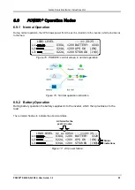
Figure 18: AC power failure indication
6.9.3 Bypass Operation (Automatic)
During Bypass operation, the ac feeds the load via the bypass static switch. The red alarm flashes to
indicate abnormal status.
LOAD LEVEL ---12:01:11---
L1: _____ 030A, 120V BATTERY: 432V
L2: _____ 029A, 120V UPS OK (ON)
L3: ______ 022A, 120V STSW OK (BYP)
Status
indications
Figure 19: UPS in Bypass mode
Figure 20: Red alarm flashing
6.9.4 Bypass Operation (Manual)
If the Power+ is manually switched to bypass operation by pressing the Inv/Byp button, the load is
transferred to the mains ac input line. Transfer back to normal operation must be performed manually. The
red alarm indicator flashes (Figure 20).
6.9.5 Emergency Power off – EPO (Manual)
The EPO button is for use by the user, in emergencies only. The EPO button cuts the supply to the load
with immediate effect and cannot be reset. Once switched OFF by the EPO, the
POWER+
must be
restarted manually.
See section
7.6 for more information on use of an EPO switch.
Содержание PowerPlus RM 100
Страница 27: ...Gamatronic Electronic Industries Ltd POWER RM100 3X208 V User Guide 1 3 13 Figure 7 Battery cabinet wiring...
Страница 44: ...Gamatronic Electronic Industries Ltd POWER RM100 3X208 V User Guide 1 3 30...
Страница 81: ...Gamatronic Electronic Industries Ltd POWER RM100 3X208 V User Guide 1 3 67 Figure 82 Service sub menu...
Страница 174: ...Gamatronic Electronic Industries Ltd POWER RM100 3X208 V User Guide 1 3 160 Table 21 List of SMS commands...


