


G
AMATRONIC
E
LECTRONIC
I
NDUSTRIES
L
TD
.
8
Power+ PREMIUM, Installation Guide, rel.
1.7
2.3.5
Connecting the UPS
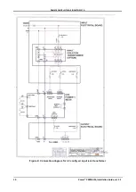
Figure 4 illustrates the UPS’s main input and output terminals.
L1
L2
L3
N
L1
L2
L3
N
L1
L2
L3
BYPASS AC INPUT
3x400 V, 50/60 Hz
RECTIFIER AC INPUT
3x400 V, 50/60 Hz
OUTPUT
3x400 V, 50/60 Hz
Figure 4: Ac terminals on 50 and 100 kVA models
1.
Connect the rectifier ac input, bypass ac input, and output cables.
2.
Use a torque wrench to tighten the terminals to 270 lbs/inch.
Note: Use copper conductors only.
WARNING! RISK OF ELECTRICAL SHOCK OR INJURY!
INSTALLATION IS TO BE PERFORMED ONLY BY A QUALIFIED TECHNICIAN!
USE REQUIRED WIRE SIZE ACCORDING TO LOCAL CODES.
SEE FIGURE 5 FOR MAXIMUM CURRENT LEVELS.


