Gamatronic Electronic Industries Ltd.
50
Power+ Technical Guide
3.
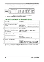
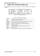
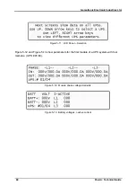
Ensure that you have a normal reading on the System Controller display. The bar graph
on the left side displays loads of all 3 phases as shown in Figure
Power up
Default
window
Figure
4-7: Normal display of the controller LCD (default)
4.
Switch all battery switches ON on all battery cabinets.
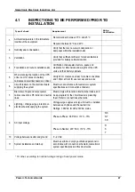
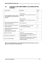
Checks to be performed following initial startup
Type of check
Requirement
Phase to Phase:
Not less than 2% below no-load values measured in item 5 below.
1.
AC input voltage during operation under load.
Take measurements on the input terminals of
the system
Phase to Neutral:
Not less than 2% below no-load values measured in item 5 below.
2.
With no load on the system, measure current
circulation between the units.
I
rst should be <15 A
3.
With no load on the system, measure the DC
voltage of the system.
Total DC voltage b and
–
terminals should be
between 850 V and 880 V.
4.
Voltage between neutral and ground during
operation under load
On the input terminals of the system
0–2 VAC
5.
System output voltage
220 V +/- 2 %
or other according to system specifications
6.
Total system load / output current
Verify that the system is not overloaded in relation to system
specifications
7.
Correct and orderly operation
Verify that the UPS is operating normally in accordance with this
User Guide and that no alarms or fault indications are evident
NOTE: It is the responsibility of the customer to notify Gamatronic Electronic Industries Ltd. and receive
approval for any deviations from these requirements.
Содержание POWER PLUS
Страница 13: ...Gamatronic Electronic Industries Ltd Power Technical Guide 5 Figure 2 2 Block diagram of a single UPS Module...
Страница 19: ...Gamatronic Electronic Industries Ltd Power Technical Guide 11 Figure 2 8 System controller Block diagram...
Страница 26: ...Gamatronic Electronic Industries Ltd 18 Power Technical Guide Figure 3 4 POWER System Rear View...

