G
AMATRONIC
E
LECTRONIC
I
NDUSTRIES
L
TD
.
CENTRIC 3x480, User Guide, rel. 1.7
93
9.
O
PERATING THE MAINTENANCE BYPASS SWITCH
Maintenance bypass is an optional feature. In maintenance bypass mode, the UPS output terminals
continue to supply power to the load, but the interior of the UPS is isolated from all power flows. This
enables a technician to work safely on the UPS (after turning off the battery circuit breaker or disconnecting
the battery fuse) without any interruption of power to the load.
When present, the three maintenance bypass switches are located on the Centric’s rear panel.
9.1
Putting the UPS in maintenance bypass mode
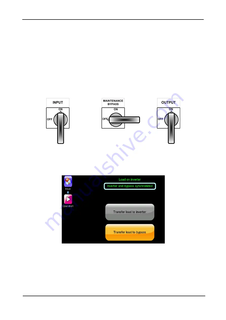
During normal operation of the UPS, the maintenance bypass switches are positioned as shown in
Figure 76.
Figure 76: Normal position of the maint. bypass switches
To put the system in maintenance bypass mode:
1.
Go to the “Operation > Transfer Load” screen. Verify that the message “Inverter and bypass
synchronized” is displayed near the top of the screen. (If it is not, you cannnot continue.)
Figure 77: Inverter and bypass synchronized
2.
Select “Transfer load to bypass”.
3.
Return to the Status screen and verify that the UPS is in bypass mode.


